The problem of obtaining good quality overwriting video from VHS, containing the first copies, of concern to many videolyubiteley. To resolve this objectives the authors of this article propose to use the regenerators synchronization signals of the video signal.
Fans of movies often have to deal with overwriting them both the VCR and the computer. And there is a big disappointment if the copy turned out to be of poor quality or doesn't work. To improve it or even to be write protected, if use a discussed below device.
It should be recognized that virtually any analog method overwriting video and audio copy is always worse than the original. The reasons are many, but to mention all of them here seems inappropriate. You only need note that as a result overwriting of the video signal deteriorates not only the clarity image, but to a far greater extent it is in sync. So after the third copy, you notice a horizontal jerking of the image especially in bright areas. Obviously, if present in the original pulses of copy protection, then do not overwrite it. When recording video to the computer requirements for the quality of the clock even tougher more.
In professional practice for correction of synchronization signals used digital clock regenerators, restoring all temporary and amplitude parameters of pulses of the video signal. In Amateur practice quite it helps to restore the necessary amplitude and lower human clock, but only in more complex cases - and even their duration and form.
The principle of operation of the regenerators is simple: old sync from composite the video signal are removed, and in their place put the new generated special generator. Depending on the requirements of videolyrics and availability him components for option regenerator is a simple and more complex.
The basis of the first option was the device described in [1]. Principal diagram of a regenerator is presented in Fig. 1.

(click to enlarge)
The device consists of a transmission channel video and generator. The video signal reproducing apparatus is supplied to the input amplifier assembled on transistors VT1, VT2. With its output signal passes through the circuit R7C3C5 to the generator and through a chain R8C4 buffer amp on the transistor VT3, the terminating resistance input and output sections. The output stage transistors VT4, VT5. It is just provides replacement for the old clock to the new, which in this cascade through the diode VD1 is exposed to pulses from the generator. It should be noted that channel transfer in the regenerator, the polarity of the video signal is not changed.
The clock driver in the regenerator is the LM1881 chip (DD1), representing specialized multifunctional device [2]. In in our case the chip used node isolation clock, constructed by a comparator circuit, the output of which plays an additional role switch the output stage of the video transmission channel. Formed in chip and calibrated the amplitude of the sync pulses to its output (pin 1) through the switching diode VD1 arrive at the base of the transistor VT5 output stage during the appearance of the sync pulses of the video signal. As a result, the base transistor through the diode VD1 is connected with the common wire, thus achieving the removal of the interference pulses and the old clock pulses and simultaneous replacement them with new ones.
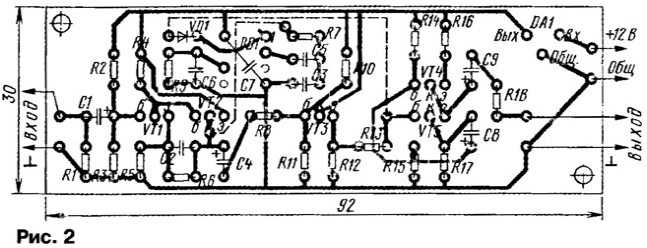
The device is assembled on a unilaterally foil PCB, drawing the conductors of which the placement of parts therein shown in Fig. 2. During installation chip DD1 her conclusion 7 buckled under her. Capacitor C7 is soldered to the terminals 4 and 8 DD1 chip from the printed conductors.

To power the regenerator may be any suitable voltage source 9... 12 V, with allowable load current 100...300 mA. If we exclude chip stabilizer DA1, it is possible to use power sources with within the voltage 4,7 7...In, for example, from the calculator electronics D2-1 OHM".
When creating a device, check the voltage at the terminals of the transistors the correspondence indicated in the diagram. The deviation from them within ±5...10 %. Then disable the output of the cathode of the diode VD1 from pin 1 of the chip and DD1 turn your device into the path of the video signal. If everything is assembled correctly, control your TV should observe the same image as and without device. Then without turning it off, connect the broken chain between the diode VD1 and DD1 chip. The image control on the TV is to move to the right 1...5 mm, which is indicative of normal operation the regenerator.
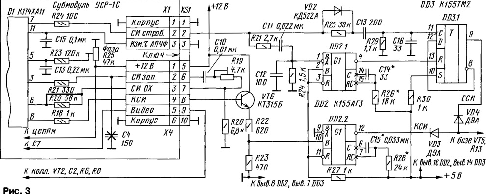
The second option is more complex regenerator has a video transmission channel, similar to that described above. The changes affected only the generator, which in this case not only restores the amplitude of the sync pulses, but corrects their duration. Its schematic diagram is depicted in Fig. 3 (the numbering of elements in the diagram continues the numbering of the parts is simple regenerator). The basis of the generator was taken as part of the translator cable television TRS-06 P/S.

(click to enlarge)
As the node separation of the sync pulses from the video signal instead of chips LM1881 applied module SRM-1C, used in TVs the third or fourth generations and assembled on the chip CHA or its analogues [3]. Received in module personnel triggering pulses from pin 8 of the connector XS1 through a matching the transistor VT6 are on a single-shot DD2.2, forming new personnel the clock (XI). Gating the horizontal sync pulses from pin 2 connector XS1 served on a single-shot DD2.1 and the trigger DD3.1, which forms new lowercase sync (IDS). Lowercase and HR clock summarized after the diodes VD3, VD4 and affect the video transmission channel.
For this variant of the device requires a voltage source of 12 V with a current loads up to 300 mA. It can be assembled on any well-known scheme or apply the finished product.
In a more complex embodiment, the device is made of three boards. On the first tab assembled the video transmission channel. It is similar to the previous option, only it does not establish the details relating to his generator: R7, R9, C3, C5-C7, DD1, VD1. The second motherboard module FCP. On the third Board (the author is not printed developed and used a breadboard), set the remaining elements generator.
Before applying you must check the efficiency of the SRM module. For this serves him food and video. If all exits are required pulses (checked with oscilloscope), the module can be used. Unfortunately, defective products will be on sale a lot.
In addition, before using the module FCP, make him small changes. First, you need to wire a jumper resistor (56 Ohm), included between pin 6 of the chip CHA and pin 3 of connector X4 (R20 in [3]); and secondly, remove the capacitor (150 pF) connected to the wire that goes to the contact 2 of the connector (C16 in [3] or C4 on industrial circuits TVs).
The establishment of a second embodiment of a regenerator begin with checking the operation of the channel video transmission as described above. Then it connects the entrance generator oscilloscope and check the presence of pulses at pin 12 the single vibrator DD2.2 (XI) and the output 9 of the trigger DD3.1 (Jia). If necessary set the pulse width of the selection elements C14, R26 (4,4...5,1 ISS for Jia) and C15, R28 (192 µs for XI). When recording video programs on the computer when unstable frame synchronization (slow motion shots vertically) you can try to increase the capacitance of the capacitor C15 to 0,068 UF. When the connection of the anodes of the diodes VD3 and VD4 with the base of the transistor VT5 on the image control the TV connected to the output of the device has to shift as it was stated above.
In both cases, perhaps the use of series transistors KT315, KT361, KT3102, CT appropriate structure with any letter index. Resistors - MLT-0,25, capacitors - any suitable dimensions. Diode VD1 in simple the regenerator and the diodes VD3, VD4 in the complex must be GE: D2 or D9 with any letter index.
Work both options are roughly similar. The author checked them performance when recording of a noisy video signal to the computer. In both cases, the quality of the recorded images was much higher than when direct recording.
Literature
Authors: A. Vorontsov (RW6HRM), A. Korotkov (RA6FER), Stavropol


