The complexities of Troubleshooting in TV, especially in block horizontal, familiar to many Amateur radio operators and repairmen. For them the decisions of the author of published article here offers a simple to use tester. It allows you to check not only the output stage horizontal teleuision and monitors, but switching power supplies, and also included in such devices are inductive elements.
Repair of TVs, especially modern ones, are often found fault finding and elimination of which causes certain difficulties only radio, but also TV technician. A good percentage associated with defects horizontal. Very urgent this problem began with the advent of the domestic market, and hence in repair shops, TVs with digital control and signal processing, as the search process and Troubleshooting them is associated with the specifics of their work. About this explained in detail in the book by P. F. Gavrilova and A. Y. Dedov "Repair digital TV (M: Radiothon, 1999). The fact that the slightest deviation in the modes the nodes of a horizontal sweep these TVs is causing the lock as her processors and power supply, and hence the difficulty with them starting to traditional checks.
To solve in most cases, problems allows so-called load testing output stage line scan. Offer verification can not only significantly reduce the search time of the fault, but also, most importantly, to clearly answer the question, this cascade is defective or not. Testing is carried out when the TV is turned off. It identifies the most defects lowercase transformers and deflection systems. This method of testing you can use (according to author) to check the TV as domestic and import production, with both modern and the oldest and scanners computer monitors and pulse power sources with a corresponding change of parameters of signal testing the device is a load tester.
The method of load testing is that at the output stage horizontal serve with extra low voltage (about 15 V), substantially smaller nominal and equivalent power source apparatus. The pulses at the output the connected tester, following with a frequency of, for example, 15625 Hz for TV, simulate the operation of the transistor output stage. Thus in a string the deflecting transformer and the coil oscillations are produced, quite accurately reflecting on his work, only the amplitude arises in the currents and voltages about 10 times less than the operating amplitude.
Using this tester, as well as the meter and the oscilloscope, check the work output stage. Practice shows that the audit when searching faults in the horizontal sweep circuits always advisable to carry out.
A schematic diagram of a load tester is presented in Fig. 1. His field transistor VT1 plays the role of a power switch, plug-in required polarity to the transistor output stage line scan. On the shutter field-effect transistor receives the pulses from the master oscillator, harvested chip DD1. Pulse width adjust variable resistor R4, and the frequency - variable resistor R1. The SA1 toggle-switch is suitable for switch test: "Test." or "Continuity test" (this mode will be told next).
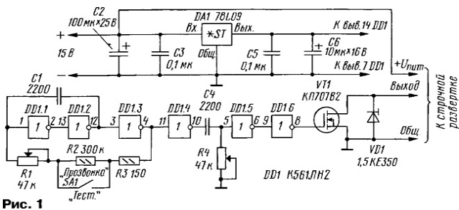
In test mode the frequency of the generator is put equal to the operating frequency pulse Converter of the investigational device. For line scan the TV it is equal to 15625 Hz and the VGA-monitor can be 31.5 kHz or higher. In the "Continuity test" the generator frequency is about 1 kHz. The pulse duration and the frequency for the TV is selected so that the open state of the field transistor was equal to 50, and a closed state is 14 µs.
Field-effect transistor is shunted by a protective diode VD1, improve the reliability tester. It is a fast-acting limiter threshold voltage 350 In protecting the transistor from high voltage surge when testing. You can certainly refuse its use, but then it will reduce the reliability of the device.
Structurally, the tester is made in the form of a Board with a separate power supply. The tester is assembled on the PCB of one-sided foil fiberglass, the drawing of which presented on Fig. 2.
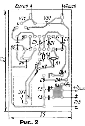
The device incorporates variable resistors JS4-1, or any other suitable in size, fixed resistors MLT, ALT, C2-OPA, etc. Capacitors C2, C6 - any oxide with minimal leakage current, and the rest - K10-17, or km. The capacitor C5 soldered between the power pins of the chip DD1 either side printed conductors, or with side parts, placing it over her. As output pins ("Output" and "Total") used flexible contacts from connectors length 15 to 20 mm.
The establishment is reduced to the labeling frequency and pulse duration, the relevant test modes on scales of variable resistors.
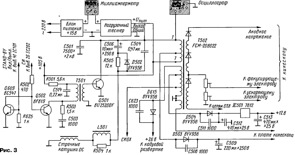
Load tester "hang" on the Board check the device soldered two flexible output ("Output" and "General") tab to soldering points collector and emitter the output transistor (respectively) tested horizontal way seen on 1st S. cover. Thus it is necessary not to forget to supply voltage (+U n and m = 15 In) at its output stage. The scheme of connection of the tester and measuring devices to cascade horizontal on the example of imported TV presented on Fig. 3.
The power supply tester may be any source of DC voltage 15 V capable of providing current up to 500 mA.
Move on to the verification horizontal sweep. At first check (with an ohmmeter) the transistor output stage breakdown. If he punched before testing should unsolder. In good condition, the transistor does not affect the meter readings.
Connecting the tester (according to the scheme in Fig. 3), measure the current consumed weekends cascade. If the milliammeter will show a value in the range 10...70 mA, it OK for most output stages. Less 10 mA value indicates the presence of the cliff in chains, and more to 70 mA (especially more than 100 mA) - increased current consumption output stage, a flyback transformer or other circuits, loading main power source of the apparatus. The TV was switched on, if you do not understand the reason of the phenomenon is likely to cause either protection of power supply or failure of the output transistor. In this case need to figure out why increased current consumption.
(click to enlarge)
Reduced power consumption usually associated with cliffs in the elements and circuits of the output cascade or consumers of energy converted flyback transformer, for example, in the frame scan. With the increased consumption of need first to determine how current it is called - is a variable or constant. To do this, they measure in two modes: AC - when the connected tester, constant - off (closed) state of its output transistor. To obtain the second mode can be a variety of ways. For example, just unsolder conclusion "Exit" from the horizontal (as did the author). However, for the same purpose you can set the slider to the resistor R4 in the highest (the scheme) position or to provide power, shorting this resistor is shorted.
Consumers increased DC are the capacitors leak, punched semiconductor elements or winding in the output circuit linear transformer (FA). Increased intake of alternating current caused most often the interturn short circuit in the fuel Assembly, deflection systems or other the reactive elements, and a leak in the secondary circuit of the fuel Assembly.
To find a short circuit or a leak in the secondary circuit of the fuel Assembly, when the measurement of the rectified voltage, you can use a DC voltmeter current. It should be remembered that the load tester only mimics the output cascade horizontal when the supply voltage is significantly lower than nominal. In this case, all the secondary rectified and the pulse voltage will be to have values that are approximately an order of magnitude-less nominal.
If the measured pulse or DC voltage is significantly lower, then you need to check the elements in the circuits: a filter capacitor or rectifier diode and the chip frame sweep (if it is powered by a fuel Assembly).
However, to focus only on the current consumption for the final decisions about malfunction or performance line scan cannot. More precisely, low current consumption does not always indicates a healthy lowercase sweep. So, identified a number of defects when when testing current consumption remains within normal limits. For example, in the SONY TV - KV-2170 when the closure winding diode-cascaded flyback transformer (TDKS) on the 24V (power vertical) supply current 18 mA increases up to 26 mA, and filament winding circuit at the same TDKS causes increased current to 130 mA. This is probably due to the different arrangement of the coils on the yoke TDKS and different inductive relations with the main winding. In addition, for example, in PHILIPS TV - TA supply current line scan was equal to 74 mA, and disconnect all loads have reduced it only to 70 mA. Again, this is not allowed to unambiguously judge the state of the cascade.
More accurate to conclude that the fault allows the oscillogram of pulses reverse at the collector of switching transistor. The oscilloscope can also to measure the duration of these pulses, which depends on the circuit from the output cascade, mainly the flyback transformer, capacitors, flyback, deflecting coil and connecting a capacitor in the circuit of the deflection coil. The pulse duration indicates whether the line circuits transformer and deflection coils need timing and made if the resonance.
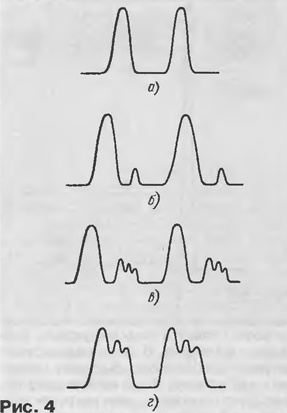
With proper horizontal sweep pulses are observed correct form without spurious resonances and spikes, as in Fig. 4,and. If their duration within 11,3 15,9...ISS, it's safe to say that the output the cascade forms a normal flyback pulses.
Punched diodes, inter-turn short circuits necessarily distort the waveform. When the circuit in the load circuits, the oscilloscope has the form as in Fig. 4,b. In the breakdown rectifier diodes waveform looks like the one in Fig. 4, or G.
When the results of stress testing will show the presence of faults in the output the cascade horizontal, repairman, of course, will want to check it out components, including the flyback transformer and deflection coil. But if found only a small deviation from normal load and the duration pulses, with these key components, most likely all right. In this case there is no need to spend time on their testing. Better to continue measurements with the TV on and find the source of the fault. So it will be much faster.
One should keep away of the touch of the hands of elements of the sweep when testing as with the load tester on the collector of the output transistor, conclusions the flyback transformer and multiplier arise still pretty high voltage.
There are faults in which the pulse duration may be on the boundary of valid values or even change. This may indicate either a weak shunt windings of the transformer, or on the precipice of some from loads.
Check the considered method can be of great help when replacing lowercase transformers and deflection systems, when you cannot find the original detail and have to settle counterparts.
The method of load testing can identify such rare problems as flickering circuit. They are mainly associated with defects of the elements which occur sporadically. One such defect is the chafing of the insulation of coils overheated, badly stretched or loose on the technological requirements the windings of pulse transformers. Uneven heating of the windings and their expansion, bearing vibration in a magnetic field, create the conditions for local the destruction of the insulation and the occurrence of flickering of interturn short circuits. Then power transistors fail like all of a sudden and causeless.
These defects require special methods of diagnosis and with the use of the active mode of operation of the transformer.
We now turn to the verification of the inductive elements in the load tester mode "Continuity test", which was mentioned at the beginning.
There are many methods of resonant inspections of transformers using generators 3H. The reliability of such checks is that trying to check the transformer, exploring the shape of a sine wave or resonant frequency winding, often have only to regret the wasted time.
Because the resonant frequency of the transformer depends on the number of turns, diameter wire, material properties of the magnetic circuit, the width of the gap. Many years ago method of circuit parts of turns of the coil of the magnetic antenna (similarly to the transformer) resonance was shifted higher in frequency without too much damage to work in resonance. Therefore, short circuit, do not affect the resonance, and only increase its frequency, reducing the quality factor. Form of a sine wave in the coil with closed coils may not even be distorted. As can be observed, and several resonances.
One reliable way of checking inductive elements should be called a poll or assessment of the quality factor. When performing a continuity test parallel to the winding inductive element (flyback transformer, deflection system, etc.) connect a capacitor with a capacitance of, for example, 0.1 μf and supplies pulses to generator duration of about 10 μs and a frequency of 1 ...2 kHz. For this purpose, as once and you can use the master oscillator load tester, setting the switch SA1 to "Continuity test" and adjusting the frequency of the alternating resistor R1.
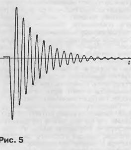
In formed by the capacitance and inductance of the transformer parallel resonant circuit occur damped after a few cycles fluctuations (say, "circuit of the rings"). The rate of decay depends on the quality factor coil. If you have a closed loop, the oscillations will last and last more than three periods. With proper coil circuit will ring 10 times or more.
The poll is the flyback transformer can be performed, even without soldering it from Board of the TV. You only need to disable the power circuit line scan. If the tested transformer is working properly, then on the screen appears oscillograph the waveform depicted in Fig. 5.
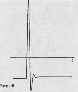
If oscillations are significantly damped faster, for example, as in Fig. 6, it is necessary to turn off the circuit loads of the secondary winding until a long period oscillations. Otherwise must unsolder the transformer from the circuit Board and finally see the results survey. It should be borne in mind that even one of the closed-loop all the coils in the transformer will not be ringing.
You can also find closed coils in the deflection systems and transformers switching power supply units.
And finally, it is necessary to say a little about checking TDKS. Features verification related to the fact that the high voltage multiplier is mounted in the transformer together with the windings. High voltage diodes multiplier can be broken torn, to have a leak, resulting in the anode and the focusing voltage can be low or absent at all, and load testing of the cascade does not clearly delineate the search box fault (winding, the magnetic circuit or multiplier). But there are ways to restore TDKS, if he punched filter high voltage capacitor. Yes and to pick up and replace the magnetic circuit from the other transformer is not particularly difficulties.
Submitting to the primary winding TDKS pulses similar to the pulses of the output cascade horizontal, it is possible to carry out dynamic testing, test, as straightened, and multiply the supplied pulses. Defective diode, or winding the magnetic core of the flyback transformer will reduce the output voltage TDKS. Dynamic testing performed by the same tester, and what a load testing. It is only necessary to regulate the voltage supplied to the primary winding of the transformer to pulse amplitude at the drain key transistor tester was equal to approximately 25 V. Measure the output voltage at the anode of the tube relative to the aquadag. It should be more than 600 V.
Values of the measured voltage in order to function correctly must meet the TDKS listed in the table.
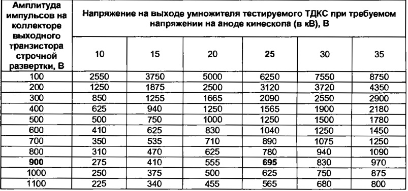
For example, if in a normal working TV the amplitude of the pulses at the collector of the output transistor horizontal equal to 900 V, and the voltage at the anode of the CRT - 25 kV, then check TDKS according to the above procedure on the output of the multiplier must be a voltage of about 695 In (in the table these values in bold).
The principle of verification horizontal sweep is the basis of many branded devices. However for the price they are inaccessible to ordinary and hams private repairers. As described here a simple tester can completely replace such devices.
Author: D. Malorum, Kovrov, Vladimir region


