How to use reception apparatus "NTV+" for receiving programs from other satellites? The answer to this question is of interest to those who would like to increase the number of the programmes, and those who for economic reasons until forced refuse to accept "NTV+".
The reception by the receivers "NTV-1000" and "NTV-2000" programmes from other satellites (e.g., with one of the five satellite "Hot Bird") is possible when using dual band (10,7...11.7 GHz and 11.7...12,75 GHz) converters (block LNB). However, the problem arises of how to manage the converters.
Band switching in these converters perform tonal feed signal (22 kHz) on the food chain. In the receivers of the system "NTV+": "NTV-1000" and NTV-2000" such regimes are not provided, so you will need to install tone generator, but they still need to manage. As for the receivers NTV-200", then this problem is solved (see article V. Ivanov, "the Revision of the tuner system "NTV+" for the reception of satellite programs "Нot Bird" in "Radio", 1997, No. 11, p. 14). As for wide receivers "NTV-1000" and "NTV-2000" she's a bit more difficult as there no special signal tone generator. Offer one of solutions to this problem.
The first thing to do is to fabricate and install the tone generator signal with a frequency of 22 kHz. It can be assembled in a more simple scheme (Fig. 1), proposed in the article by V. Ivanov - based logical multivibrator the elements DD1.1, DD1.2. The elements DD1.3, DD1.4, connected in parallel, perform the function of a buffer amplifier. Their output is installed, the integrating chain R3R4C3, which converts the square wave output of the multivibrator in exponential (close to triangular). The output signal via the capacitor C4 is supplied to the control input of the voltage regulator U303 receiver. Practice showed that for switching Converter, its amplitude should be 0,3... 0,5 V.

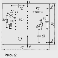
All items are placed on the PCB of one-sided glass fiberglass side wirings (Fig. 2).

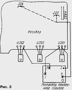
Installation option Board in the housing of the receiver shown in Fig. 3.

Board through the hole using screw M2,5 is fastened to the ledge at the bottom of the hull receiver, next to the heat sink of the voltage regulators. Power wires (conclusions 1 and 3 card generator) accurately fluster to the pins of the IC (U301) a voltage stabilizer. Circuit signal output (pin 2) is connected to the output voltage regulator implemented on the IC U303. And to pin 4 of the Board generator serves a control signal from the receiver.
As the control signal, you can use various commands with the remote control that is stored in the receiver memory. You can, for example, to use the switching command decoder. All of these four teams: "no", "d1", "d2", "d3" - they are on different tyres receiver. If submit the control signal from the Col "J23", which is connected with the connector "CON4", the tone generator is activated under the action of the first and fourth of these teams.
But it should take into account the following circumstance: if the decoder is disabled and he is not need, when you switch these commands will disappear from the image and sound scarce "TV" and the output of the RF. To avoid this, scarce "DECODER" we have to connect jumper pins 1 and 2, 5 and 6, 19 and 20. But the brightness image and volume can change.
To control you can use the button and the signal "DEV" (two-stage change the brightness of the image), but then simultaneously with switching converters automatically and will change the brightness. In this case, the signal on pin 4 tone generator is removed from jumper J36, which is located near tuner (UHF unit) receiver. The generator will start to work when the command "dR" and will turn off when the command "br" (both are displayed on the scoreboard receiver).
The establishment comes down to setting the oscillator frequency and amplitude verification output voltage. Do this before installing the generator in the receiver. The frequency of the generator (22% 2 kHz) is set by the resistor R1 and the amplitude AC voltage at the output resistor R4. After installing the engine resistor R4 should be set to the left (the scheme) position and switching the appropriate commands from the control panel, served on the control input (pin 4) the generator level of the log. 0 and to set up the receiver on one TV channels in the range of 10.7 11.7 GHz.... Then, switching teams, to apply for the control input of the generator of the signal log. 1. The Converter should switch to another range. If not, then increasing the amplitude of the output AC voltage by turning the engine resistor R4 until you get it switch.
Author: I. Nechaev, Kursk


