In the TV microcontroller control system malfunction very often associated with the emergence of defects in the program stored in the chips memory. How to identify and correct told in the published article.
Most of the problems in the repair of modern TV sets occurs because breach (failure) of the boot information (BIOS), necessary for normal work of the Manager of the microcontroller and to configure the nodes of the TV managed through digital bus (tuner, video processor, module, Teletext, etc.). Typically, this information is enclosed (recorded) in the memory node, made in a separate chip next to the microcontroller.
Currently the most widely electrically reprogrammable chip constant memory of the series type (EEPROM). Moreover, for the exchange of information between these chips is used, usually bus NS (12C), which consists of two bidirectional lines: for information data - SDA (serial data) and a clock signal SCL (serial clock). The most commonly used in TVs chip companies ATMEL, MICROCHIP, PHILIPS, containing at the end denote an alphanumeric combination S, 24C02, S, S, S PCF8582 or (domestic counterparts RR, RR,HP etc.)
Sometimes used in TVs-wire bus 3-Wire (Microwire) serial type in which the exchange of synchronization signals - SK (shift clock), I / DI (data input) or output DO (data output) data and choice crystal - CS (chip select). An example of a memory device with a bus can be called chips, which end in combination S.
Protocols and methods for addressing these tires and chip detail described in popular literature, for example, in the references chips publisher of DODECA. Here, however, they are not talking. Stop only on practical aspects.
Generally, all memory chips other model with more memory. For example, the chip S 24C02 or can be replaced by any of S, S, S. Chip C has a memory capacity of 1K (128x8 bit), and chip S - 16K. You can also change the chip PCF8582 on 24C02, but not Vice versa, as when writing to the memory PCF8582 external clock generator programming.
The existence of a fault due to a defect information in the memory chips can variety: TV does not turn on, does not appear on-screen menu or management through it is performed incorrectly, changed geometry of the raster, happens memorizing the selected program, spontaneously switch TV off sound, etc. in addition, after turning the TV on all primary set the volume, brightness, contrast and saturation can be changed at the maximum or minimum value. Test oscilloscope the presence of synchronization signals and information data in most cases is useless, since the exchange happens when you clean the chip, and when it contains incorrect data. Even one defective ("dangling") cell (i.e., which cannot be reprogrammed) may be the cause of the fault.
In the most General case, when switched on, the microcontroller control RESET signal RESET. Usually used for this purpose specialized chip reset. Then, the program recorded in the microcontroller starts with some point (not necessarily with a zero address). As a rule, after sampling two or three commands (initialization of ports, ADC, etc.) microcontroller accesses the memory chip and reads the initial installation in saoy block RAM. Usually this is the initial value of brightness, contrast, saturation, image and sound volume, information about the geometry and raster other, depending on the software functional capabilities of your TV.
Unfortunately, in developing programs for microcontrollers, there is no standardization: each firm-the developer is doing it on your own So following work options pairs microcontroller-memory chip either the processor reads all the information and after external influence, for example, commands from the remote control, turns to her, or the CPU all the time queries via digital bus the memory chip and in the intervals between polls responds to external impacts, identify the faulty link (processor or memory chip) may be difficult.
To uniquely verify the contents of the memory chips is best to use the programmer. Its use is, of course, simplified approach in such a situation, but in most cases solves the problems associated with malfunction of these chips.
Consider ways of eliminating the defect of the memory nodes at the example of the most common imported TVs FUNAI - TV-2000MK7 and SONY- KV-T14M1.
In TVs FUNAI memory chip fails due to a fault in the line scan, the memory block, lightning strike to the antenna. In this model installed chip S. After replacing the chip on the "clean" values for all settings (volume, brightness, saturation and contrast of the image) take the maximum value.
To resume the information in the memory chip in this case is off TV pin 13 of the microcontroller control (one of the series TMRS) must be disconnected from the common wire and through a resistor of 1 kOhm to connect to a point in which the supply voltage is +5 V. as a result after turning the TV on all the necessary boot factory information rearranged from the microcontroller in the memory chip. Then you need to turn off TV and to restore normal operating mode pin 13 the microcontroller again to connect the common wire.
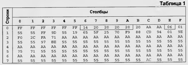
After such a "flash" memory chips with microcontroller it is the information recorded is presented in table. 1 (left and above are the addresses the rows and columns of memory cells, respectively, all numbers in the table in hexadecimal).

Decipher some boot information located in the cells that get outlined. So 0-6 at the address (row / column) the recorded volume level sound 14 N, where surly N marked value in hexadecimal form, and the addresses 0-7 - 0-a - level 20N brightness, contrast, saturation, and sharpness image.
If you don't like some factory settings, can programmer to adjust them up or down. The minimum value in these cells - 00 H, the maximum - 3H N. The information in the cell at the address 0, equal to 06 N, change is not recommended, as it is information about the system color and manipulations can be off color. Cell 0-F with the value 01N stores the channel number (in our case, the first channel). The value of 22 N corresponds to 22-th channel. Cell addresses are 2-0 for memorizing stations. In the cell on address 7-(value AC H) the information is not altered reserved a microcontroller.
After checking the chip for write-read and write factory default settings you can be sure that the memory chip is defective.
In TVs from SONY in addition to malfunctions because of these above causes, there was a change in the contents of the memory chips on unknown reason (especially in the early models). In the above model used chip 24C02. It contains more information than S. After replacing the chip with a new one ("pure") is a common problem it is a violation the geometry of the raster. In addition, problems can also arise if modifications of this TV standard PAL NTSC SECAM standards-PAL-NTSC.
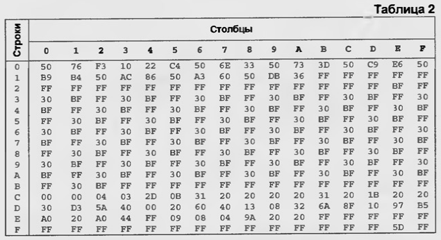
To set the correct geometry raster "flash" memory chips reflected in table. 2.

If modifications are made, you have two options. In models (European) on the video processor MS company Motorola color turned off programmatically. For inclusion in the cell by E-But need to write down the value of 20 N. In the TV video processor MS, in addition to recording on the above-mentioned value cell of 20 N, replace the video processor on MS or MS. No other alterations not required.
A little about the content of "vitally" important to the cells in the memory chip for this model. Address C-6 with a value of 31 N - level brightness adjustment. Address C-7 to C-F - factory preset. Address D-0 through D-A - all settings on geometry raster. Address D-B with a value of 6A N - lock video, D-D (value 10N) - reproduction. Address E-A (value) 20 N - color system. For off color in this cell should contain the number 7D N. In this case it must be remembered that the choice of the system, the magnitude of the three-level signal synchronization (Sandcastle) depend on the used processor.
Of course, all of the above changes can be done when entering the service mode. For SONY TVs typically require the following the combination of button presses on the remote control in the standby mode of the device: Display, "5", Volume the " + " PWR ON. To record the changes made, press the Mute button write. Wherein the memory is being reprogrammed in its entirety. However, it should remember that there is another key combination to enter the service mode for specific TV models.
Considered it is seen that in the case of programmer to check the operability of the memory chips, and its contents, as well as if necessary, and change any settings (even just one bit). Service mode is convenient when you make some adjustments (for example, in the geometry of the raster) without disassembling the TV, but we cannot be sure, what memory chip in good working order and that all content complies with factory settings. Unfortunately, brand service instructions and for many roads models are virtually unavailable. Therefore, the acquisition of the programmer or independent fabrication is advantageous for economic repair TVs. The main task consists in picking up the library "firmware" with a known-good TVs. In any case, it is preferable use the factory settings, which completely avoids any errors.
Author: A. Goncharenko, Odessa, Ukraine


