


")

To date, the presence of two or more televisions ceased to be rare. However, the joint operation of a number of problems arise, related, for example, connecting an antenna or VCR/video player. We offer two devices make it relatively easy to solve them.
"LOW-FREQUENCY" SPLITTER AUDIO AND VIDEO SIGNALS
A splitter can be used inthat case, if for some reasons VCR or VCR player cannot be connected to two or more TVs through the antenna inputs, i.e., "high frequency". It allows you to connect them the so-called "low" frequency.
Although in [1] has already been considered such a device, however it has drawbacks that limit its widespread repetition: the presence of rare (especially for province) imported chips and a bipolar power supply.
The device described here, a schematic diagram of a video channel which depicted in Fig. 1, easier to manufacture than those mentioned above. Should to say, of course, about audio channel. It is known that the audio output of the VCR or video player designed for the load resistance exceeds 1 Ohm. This audio output is connected directly in parallel to the United the audio inputs on the TV, the input impedance of which is equal to 47…50 kOhm. Therefore, the audio and not shown in Fig. 1.
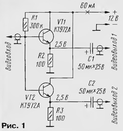
However, the video output of the VCR or the video player is designed for loads 75 Ohms, which corresponds to only one input. Therefore, to connect the two and more TVs require interchange. For this purpose, and applied two emitter repeater similar to [2]. The input resistance of their large, so you can increase their number and to connect up to six TVs.
For replacement transistors CTA you can use any of the same series and of the series CT, CT.
The device may be applied to the resistors MLT, C2-33, C2-23 or similar and oxide capacitors K50-6, K50-16 or imported. The power source voltage 12 must be rated for a current of less than 100mA.
The splitter is connected to the video equipment with shielded cable through the connectors "Tulip". Fit and thin aerial cable RK-75.
IR REPEATER
This device can be used in case VCR/VHS player already stationers connected through a splitter to two TVs located in different> rooms as shown in Fig. 2. To control the same equipment with the remote control, being both in one and in another room.
The advantage of the repeater is that it is suited to all standards The remote control Using the repeater, you can not only control videomagician/video player when playing video, but also to control the video in another room. You can also manage both TVs.
The repeater receives IR signal from remote control video recorder/video player or the TV in one room, amplifies it and transmits in the second room, where installed this equipment. Sending a signal from one room to another occurs on a cable, as illustrated in Fig. 2.
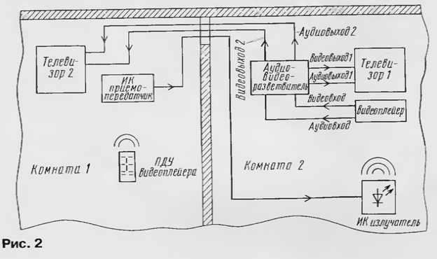
IR receiver repeater placed in the room where it is assumed to control the VCR/video player. In the repeater used IR the receiver of the industrial production of PI-5, which is used in TVs the fourth and fifth generations. The fit and any other industrial or homemade IR receiver without demodulation (this is important), for example, on a chip TWO or CRAP.
Option device concepts when using the IR receiver PI-5 presented on Fig. 3,and when using the receiver, assembled on a chip TV, - in Fig. 3,6. From the output of the IR receiver, the signal is sent to the infrared transmitter, performed on one transistor, two resistors (VT6, FM5, R16 in Fig. 3,and, VT1, R1, R3 in Fig. 3,b) and the led HL1. IR emitter NOR placed in the room in which there is a VCR/VHS player and one of TVs, and it needs to build on the object and rigidly fixed. Place mounts to choose from so that no one accidentally failed to prevent the passage of the IR signal (e.g., high on the wall near the ceiling). The emitter connect to any device with shielded cable.
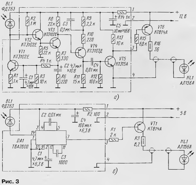
In the transistor device CTA replace any of the series CT, CT. IR the emitter ALA can be replaced by any of the series AL 147, AL 165. In the device can be applied resistors MLT, C2-33, C2-23 or similar.
LITERATURE
Author: Smirnov, G. eagle