


")

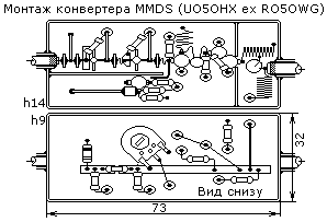
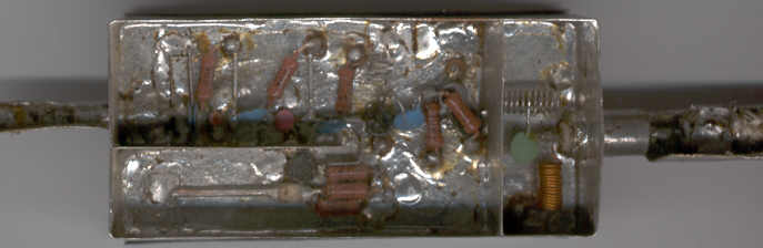
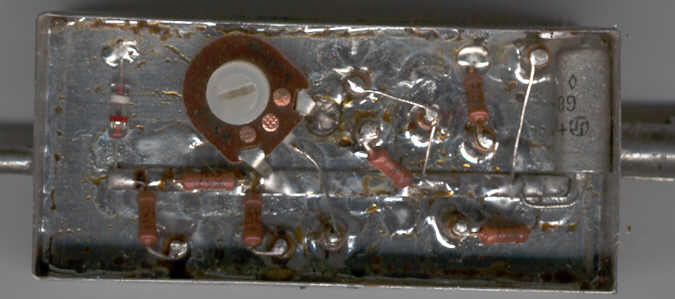
This Converter is a little different from his brother symmetric. The capacitor C3 is cropping from the Board 3x12 mm thickness 1.5 mm across the base of the output VT1, soldered to the base and the ground. C14-box of tin near the emitter VT3. All lines are raised above the motherboard at 2 mm. Power +12 is supplied via the lead-in cable through the filter similar C21L7С22. R5 to configure the mixer on VT4 quadratic plot characteristics. Coupling capacitors along with findings should resonate at medium frequencies passing through them signals. In the attention paid to this Converter, I put it on the scanner. The depth of field of course small, but something you can see.
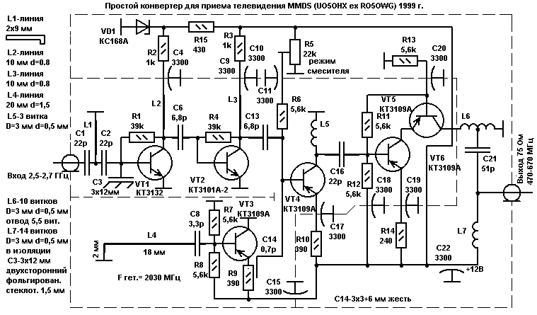
Author: E. shoustikov, UO5OHX ex RO5OWG; Publication: www.shustikov.by.ru, www.cxem.net