


")

For the reception of television broadcasts in the range of decimeter waves (UHF) TV owners, equipped with appropriate channel selectors, used mainly by individual room small-sized antenna. In this article they proposed a simple broadband zigzag [1] antenna (see Fig. 1) capable of receiving signals in any of 21-40-th channels UHF (470… 630 MHz). The leaf antenna is placed on a plate made of transparent organic glass thickness "…5 mm. Made of silver-copper wire of diameter 1.2 mm. In places of connection of the wire passed through the holes in the plate, forms a fixing cloth clamps-jumper.
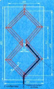
Fig.1
To the TV antenna connect a coaxial cable with wave resistance of 75 Ohm (for example, RK-75-3-31 installed along sides of the door and attached to the plate rings made from the same wire, and cloth, and inserted into the holes of the plate. The antenna fitted on the frame of the window facing the transmitting station (failure to comply with this condition, the reception quality deteriorates).
If the UHF channel selector on the TV is missing, for the reception of transmissions in this range, you need a Converter that converts the signals in UHF oscillations. take a TV in one of the channels (1-12) range of the meter will (MB). A schematic diagram of one of the variants of such Converter is designed to work together with the described antenna depicted in Fig. 2. In the middle position of the slider of the variable resistor R7 it consumes a current of 3.2 mA.
Fig.2
The Converter consists of a local oscillator and mixer. The local oscillator is assembled on the transistor VT1 scheme of capacitive treatacne feedback via back-smeshannyi diode VD1 [2], which simultaneously performs the functions of a setting item of the Converter. When you move the cursor of the variable resistor R7 changes the current through the transistor VT1, and therefore, the reverse voltage on the diode VD1 and the tuning frequency of the resonant circuit of the local oscillator, which serves as the unbalanced transmission line L1.
The lo signal through the resistor R2 is supplied directly to the base of transistor VT2 mixer, allowing to do without the additional strip line of communication and to ensure the sustainability of the mixer to the excitation. At the base of the same transistor through a capacitor C2 is supplied and the signal received by the antenna UHF.
The voltage difference frequency is amplified by the transistor VT2, selects the matching circuit L2C3R6 and via a coaxial cable with plug XW2 at the end of the inlet of the TV, working on one of the free ones (3-5) channels MB.
The voltage of the battery GBI ("Krona". "Emery," etc.) is supplied to the Converter via coaxial cable RK-75-3-31 (braid and center conductor) and an input matching resistor (75 Ohm) TV. Will glow indicating that the inclusion of the Converter, the led HLI. To turn it off enough to remove the plug from the antenna input of the TV.
In the Converter resistors are used SP-1 (R7) and IFL (other), capacitors KCM (C3) and 500 Ml or M (the rest). The coil L2 is wound on the resistor R6 and contains 12 turns of wire PEL is 0.27 with a branch of the middle.
Details of the Converter are placed on the PCB of bilateral foil fiberglass 2 mm thick (see Fig. 3). The connections of the elements with foil shown by dots. Not marked they connect two or four pins are on Board.
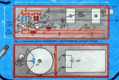
Fig.3
Printed conductors on the circuit Board is cut by the cutter width 1.3 mm. In diameter holes 1 mm inserted pieces of tinned copper wire of diameter 1 mm 0.8…and carefully soldered on both sides. The buildings of the transistors VT1 and VT2 are installed in holes with a diameter of 6 mm. Connecting cables pressed (with M3 screws) to the Board of U-shaped metal straps.
The side walls of the Converter is made of plates-sided glass Micarta, foil facing the inside of the case and soldered on both sides around the perimeter (see Fig. 3). In the upper compartment of the housing depth of about 17 mm mounted are soldered to the circuit Board and the plates of the housing partition. To her and to the body of the Converter soldered to a lead cover and bent the mounting tabs of the variable resistor R7. HL1 led is inserted into the hole of the end wall. The compartment is closed by a cover with a hole for the engine resistor. Both covers of the Converter is fixed insulating adhesive PVC tape. The design of the Converter shown in Fig. 4.
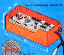
Fig.4
Establishing device start with checking the operation of the oscillator. For this to the plug XW2 connect avometr operating in the measurement mode current. During normal operation, transistors VT1 and VT2 currents in the extreme positions of the engine variable resistor R7 should be changed from 2.4 to 4.4 mA. On the normal operation of the local oscillator can be measured by the current change when you touch the blade of the screwdriver or tweezers output collector of the transistor VT1 in any position of the slider of the resistor R7.
Having done these operations, the Converter is connected to the TV, included on one of the available channels (3-5) range MB. The slider of the variable resistor R7 is set to the middle position and by moving the jumper on the line L1, roughly tune the Converter to take on this channel the program the DMV. On the Board shows the approximate position of the jumper for the reception of the 3-5 channels. If you wish to configure the Converter to one of the 6-12th channels rearrange the jumper in the position close to that shown in Fig. 3 by the dashed line.
For the reception of programs for coverage UHF antenna must be installed on the mast outside the house. To reduce the losses in the feeder next to it should be placed and Converter. As a result, the feeder to the input of the TV will be transmitted is a signal MB. The power supply for the Converter in this case is served by the same feeder. Wiring schemes power supplies shown in Fig. 5.
Fig.5
Literature
Author: M. Iliev Moscow, P 2/88; Publication: N. Bolshakov, rf.atnn.ru