"The taste and color - no friends". Watching TV in the family can cause strife. For simultaneous viewing of different programs required the simultaneous operation of multiple TVs in the apartment. However, the work of the TVs connected to the same feeder General antenna (individual or collective), without splitter causes mutual interference due to the beating frequencies of the local oscillators of receivers (modern receivers - all superheterodyne). This interference manifests itself in the form of standing or slowly moving on the screen of oblique dark lines. Published below the article will help you to find a way out in this situation.
In the collective antenna high-rise building interference are eliminated by the installation in the feeder gap storey coaxial cable splitters (Fig. 1A), which essentially are RF transformers T1 distributed along the joint of the coaxial lines inductance and capacitance each. Moreover, the outputs and inputs of each line is loaded by a resistance equal to the wave (typically 75 Ohms). The latter is provided in lines mode traveling electromagnetic wave, and the lack of galvanic connection of individual internal conductors 1, with overall braid 2 provides mutual interchange of signals in the circuit there is no General non-linear elements that are mandatory in every superheterodyne).
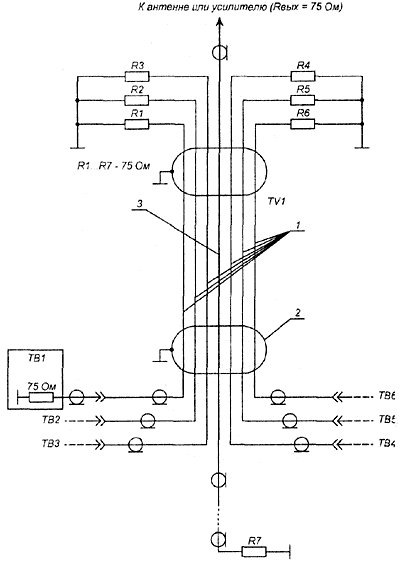
Fig. 1a. The collective scheme of distributing TV feeder
In passing it should be noted that the one who connects the coaxial cable to the trunk 3 (gilet thick coaxial cable that connects the floors), interferes with all the TV connected to the collective antenna. Therefore, if you appeared on the screen such interference, and the signal is weak, a "specialist" connected to "trunk". Immediately contact the owner of the collective antenna (in the service of the antenna). He summons the offender to order seal storey splitters. In no case do not look the intruder yourself, if you do not want an enemy in the house.
Connecting additional (family) TVs to free outputs storey/s fanout/her individual coaxial cables provide from mutual interference and none of the neighbors won't trouble you, but, certainly, inside the apartment additional coaxial cabling through the apartment to each TV is very uncomfortable (as an exception - rooms on either side of the Central entrance to the apartment).
Ham radio operators were proposed [1,2] simple TV signal splitters, such as [1] storey (Fig. 1B), but in fact the resonance (not wideband, 1.2 per channel) and frequency-independent resistors (Fig. 2A), where

a z a (usually 75 Ohms) - impedance of all cables used, n is the number of connected TV.
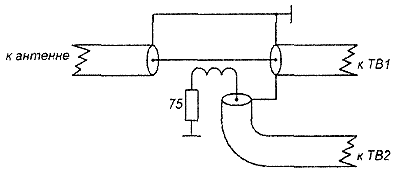
Fig. 1B. Resonant storey splitter
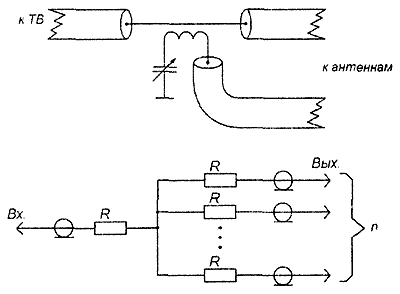
Fig. 2A. Frequency-independent distributor
To shorten the connection (to reduce parasitic capacitance and inductance), it is convenient to use separate resistors and resistive blocks b [3], connecting the resistors in them in pairs in parallel (Fig. 2B,C) or three (Fig. 2G). Such splitters are good to use if the signal is strong (antenna near or TVC is a powerful amplifier, Converter).
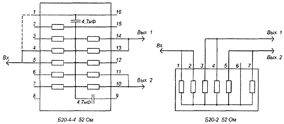
Fig. 2B. Splitter-based resistive block b with pairwise-parallel connection of resistors for the outputs for two TVs
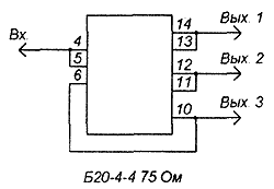
Fig. 2B. Splitter-based resistive block b with pairwise-parallel connection of resistors for output on three TVs
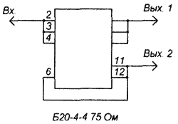
Fig. 2R. a Splitter-based resistive block b with the connection of three resistors for the outputs for two TVs
Without violating copyright for the use of Amateurs can repeat industrial television device fanout UTR-2.H2 [2] (Fig. For), the obvious advantage is the absence of losses and the presence of electrical isolation (transient attenuation between outputs, signals which are in opposite phase, and the output (1...12 channels) in the direction of 21 ...60 channels, you can continue by installing the capacitors C2, NW KD-1 to 5.1 pF crosstalk between the outputs is not less than 18 dB.
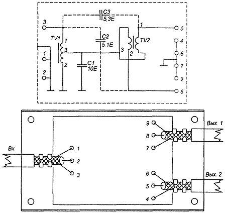
Fig. 3a. Scheme splitter UTR-2.H2
The transformers T1 and T2 are identical and are wound with two wires 5 turns of wire sew-2 with a diameter of 0.47 mm directly on the rings with rounded edges (grind round needle file) ferrite VN CHH (used in computers BESM-4, the transformers blocking-oscillator frequency dividers) [4].
Braid all the cables (input and output) cable should be securely connected together and the metal housing of razvetvitelya, and their Central cores directly on the findings of the unit b Resistor R1 type MLT-0,125 150 Ohms.
If your TV has two separate antenna input VHF and UHF, then it connects to the separate outputs of the MORNING, separate cables with a characteristic impedance of 75 Ohms.
The disadvantage of UTR-2.N2 is that for a splitter with 3 outputs will require two fanout MORNING; 4-3; 8-7 (Fig. 3b)
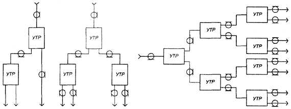
Fig. 3b. Circuits splitters 3, 4, 8 outputs
Note: capacity in blocks b-4-4 is not used, but very weak signals can be connected, as indicated by dotted lines (Fig. 2B) Scheme b-4-4 for all the resistors are identical. Ferrite rings can be type WIN any diameter, the wire diameter is not critical, just so more convenient for the installation and spooling. As a body, for fanout MORNING, you can apply part of the housing of the capacitor [5] KBG-MN 8 UF 200 or similar In size. Of course, in one case you can put 2 and scheme 3 (Fig. For) when you need a splitter for 3, 4 outputs and branching of cables from one place conveniently.
Literature
Author: N. The Ivashin, Minsk; Publication: www.cxem.net


