Readers often have to face the fact that their interest (or repaired) equipment, especially foreign production, not attached no technical descriptions, principled and even structural schemes. This creates an almost insurmountable difficulties in the repair, and even more repetition and improvement of such devices. However, the exit can be found. How to do it, is told in the article on the example of the expander Mega Key-2" for the popular 16-bit video gaming Sega Mega Drive and Sega Mega Drive-2". The author was able not only to understand how it works, but to make a similar device from the available parts.
Amateurs play on 16-bit video game Sega know that some cartridges work only being connected through an the expander. These include, for example, licensed the TV series "Super Sonic", "Earth Worm Jim", etc. the thing is that consoles Sega, and cartridges for them depending on the television standards adopted in different countries, available in several versions. Dilators "Mega Key" provide them compatibility.
Anyone who thinks that "Mega Key" means "very big key" is likely to wrong. A more plausible translation "key for "Mega". Externally the extender very similar to the normal game cartridge, but it has two small slide switch and two 64-pin connector: plug (it can be inserted into the slot "CARTRIDGE" prefix) and the socket for the cartridge.
Switches you can select one of several television standards differing number of rows of the image decomposition, the frequency of HR sweep, ways of encoding color information. Usually on the body the extender or in the manual there is a table similar to table. 1, in which the countries are listed or television standards and the relevant the position of the switches. For example, the "USA & BRAZIL" refers to the standard accepted in the United States and Brazil (525 lines, 60 Hz). "JAPAN meets common we have Asian models "Sega" (625 lines, 50 Hz). Sometimes meet cartridges that work when installing the switches into position "PAL & FRENCH SECAM".
Table 1
Standard The position of the switch SA1 The position of the switch SA2 USA&Brazil OFF ON Japan OFF OFF PAL&French SECAM ON ONCurrently, the most popular extender"Mega Key-2", working with the prefix "Sega Mega Drive", and with it an improved version of Sega Mega Drive-2". To understand its device is not easy, as most nodes inside a specialized chip chip. Manufacturers understandably in no hurry to reveal the secrets. You have to consider the extender a "black box".
Recall that in the so-called Cybernetics system in which the external the observer only available input and output signals and the internal device whatever reasons unknown [1]. Let us try to understand the structure and principle operation of the expander, using physical, logical and temporal levels analysis. The method described below can be useful in the study of the most a variety of electronic devices.
PHYSICAL LAYER
First of all, it was necessary to analyze the topology (figure) printed card extender, to make its basic circuit, measure voltages, currents in various circuits. It turned out that each of the 64 power plug expander connected directly with the corresponding contact sockets. Inserted here the cartridge is associated with the prefix is exactly the same as without extender. Parallel 29 of 64 contacts connected logic unit. It schematic diagram, compiled as a result of studying the PCB, it is shown in Fig. 1. The names of the input (A0-A22, WE2) and output (D0, D6, D7) signals and power circuits (+5 V, GND) correspond to consoles "Sega" [2].
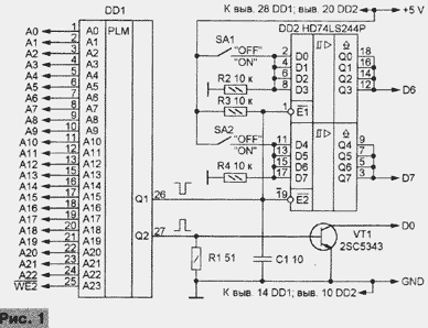
The framework is a 28-pin chip DD1 chip, potted. The numbering of its conclusions conditional on the scheme. The low level of output Q1 allows the job of bus driver DD2. The status of outputs connected to bits D6 and D7 of the data bus of the main processor of a video game console depends on the position of the switches SA1 and SA2. A high level at the output Q2 of the chip DD1 opens the VT1 transistor, the collector of which is connected to the discharge bus D0 data. If necessary, the chip DD2 can be replaced by CAP, and the transistor VT1 - CTB.
The current consumed by the expander circuit +5 V at rest, equal to 25...35 mA. Of this amount DD1 is not more than 0.3 mA. This suggests that she, most likely, manufactured in CMOS technology.
LOGIC LEVEL
The next stage in understanding the logic of the extender, to create a model the internal structure of the chip of DD1 chip.
Signal waveforms observed during the operation with the real game cartridges show that the output Q1 of chip DD1 at the moment of inclusion power and pressing the RESET button usually appear single pulses negative polarity. The output of Q2 during the game visible to non-recurrent the sequence of pulses of positive polarity and a large duty cycle.
We can assume that DD1 - decoder with two outputs, the signal at each of which indicates the processor to handle some of the memory cells. But to determine the addresses of these cells, it is necessary to try all possible combinations input (address) signals, analyzing the state of the outputs.
24 the inputs of the decoder are possible 224=16,777,216 combinations of signals. It is clear that to sort them manually in a reasonable time is impossible - this operation must automate. The analysis time of each combination should not be too small (you can skip the response), but not too big (long wait for the result). In Fig. 2 shows a diagram of a fairly simple device, allowed to spend the entire cycle of measurements per minute. It can also be useful for studies of other digital input nodes.
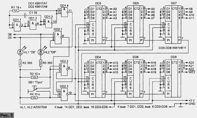
The master oscillator (DD1) operates at a frequency of approximately 500 kHz. Through logical elements of the chip DD2 connected with him 24-bit binary counter (DD3-DD8), which outputs should be connected to the corresponding inputs on the extender. When the emergence of low level signals at the outputs D0 or D6 last element DD2.1 blocks the account. At the same time lights one of the LEDs (HL1 or HL2), by showing what the chain recorded a response.
In this state, should be measured logic levels in circuits A0-A22. This code and will be the cell address memory space or I/o processor, with address to which "triggered" the decoder. Low at this point level signal WE2 suggests that the data is probably written, high - what are they read. After clicking the button SB1, the search continues. The trigger from elements DD2.2 and DD2.3 eliminates "chattering" contacts button.
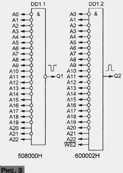
Experiments have shown that the extender responds to the input signals in two cases: when reading or writing data at the address 508000H and when reading them address 600002H. In the first it changes in accordance with the position of the switches SA1 and SA2 status bits D6 and D7 of the "real" cells, located in one of chips top box or cartridge. The second one translates into the condition logic 0 D0 discharge. I must say that it is "illegal" way: signals of relatively low-power buffers the data bus of the console are suppressed strong signals of the expander, in which the four elements of the tire shaper are connected in parallel.
Obviously, from the code at the address 508000H depends on the choice of gaming software driver or another TV standard. If the position of the switches the extender is not correct, the program stops, moving on the screen legend, such as "Developed for use with NTSC Mega Drive systems only" ("Developed for use only in systems "Mega Drive" NTSC").
The equivalent circuit of a chip of DD1 chip, the resulting analysis the extender at the logical level, as shown in Fig. 3. It consists of two input elements DD1.1 ("AND-NOT", address 508000H) and DD1.2 ("And", address 600002H).
TEMPORARY LEVEL
It remains to determine the allowable amount of delay signals in the expander, artificially increasing it until failure. This can be done, for example, incorporating multiple series-connected inverters to break the wire, connecting the output Q1 of the decoder DD1 (Fig. 1) with the input E2 of the tire driver DD2. To keep the polarity of the signal, the number of inverters should to be even.
The experiment showed that the extender is stable even with 12 elements chip K561LN2, connected in series, which corresponds to the delay signal 0.5...0.7 µs. Can assume it is not critical to the performance used active elements.
HOMEMADE EXTENDER
So, understanding the device and the principle of "Mega Key-2", to develop its counterpart on chips wide application. One possible schemes of homemade extender shown in Fig. 4. Function decoder "brand" extender in it performs a logical node on chips DD1-DD5. He also, if necessary, can be used to replace a failed unpackaged chips. In this case, the DD5 pin 8 should be connected to the inputs 10 and 11 of the free element chip DD4, and the signal Q1 to take exit 8.
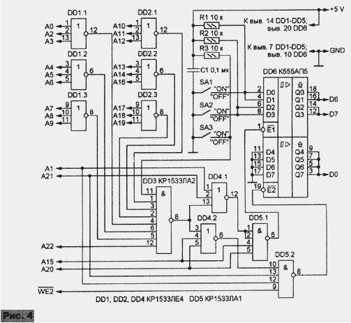
Connected to the line D0 of four elements connected in parallel to one half tire DD6 driver allows you to "save" the transistor. For lines D6 and D7 were sufficient to connect two elements of the other half.
Switches SA1 and SA2 continues to set the TV standard. But in the described device they are connected differently than in the "brand", and "ON" (PL. 1) now corresponds to open, and "OFF" - closed switch. When the closure of the contacts of the switch SA3 outputs bus pass to driver high-impedance state and the extender does not affect the operation of the top box.
All parts of the machine are mounted on a printed circuit Board with foiled fiberglass size 75x55 mm (Fig. 5). It is designed to fit resistors MLT-0,125, condenser km-5B, compact slide switch PD9-2 or PD-1.
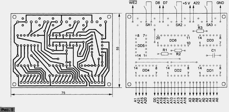
To replace the chip DD1-DD6 fit their functional analogues of the series K155, K555, CR, KR1533 and other structures TTL. As you can apply DD6 the chip not only AP5, but AP3 different series. As the latter invert the transmitted signals, pins 11, 13, 15 and 17 must be connected not with the common wire, and the positive pole of the power source. Closed the contacts of the switches SA1 and SA2 after this replacement will fit the state of "ON" and the broken - OFF.
Since the extender is connected in parallel to the circuits of the console and turned off condition does not affect her work, sophisticated transitional devices, like "Mega Key-2", to do. The PCB is recommended to be placed inside the top box (for example, near the outlet of the "SYSTEM"),securing it thus, to open the side cover you can manage the switches SA1-SA3. Contact pads of the input and output circuits of the expander must be connected according to the table. 2 contacts with any of the connectors "SYSTEM" or "CARTRIDGE" or directly with the conclusions of the MC68000 microprocessor.
Table 2
Chain Contact connector System The pin of the connector Cartridge Conclusion MC68000 A0 A3(6) A17(34) 29 A1 A4(8) A15(30) 30 A2 A5(10) A13(26) 31 A3 A6(12) A11(22) 32 A4 A7(14) A9(18) 33 A5 A8(16) A7(14) 34 A6 A9(18) A5(10) 35 A7 A10(20) A3(6) 36 A8 A11(22) B4(7) 37 A9 A13(26) B5(9) 38 A10 A14(28) A4(8) 39 A11 A15(30) A6(12) 40 A12 A16(32) A8(16) 41 A13 A17(34) A10(20) 42 A14 A18(36) A12(24) 43 A15 A19(38) A14(28) 44 A16 A20(40) A16(32) 45 A17 - B6(11) 46 A18 - B7(13) 47 A19 - B8(15) 48 A20 - B9(17) 50 A21 - B10(19) 51 A22 - B11(21) 52 WE A22(44) B29(57) - D0 B4(7) A20(40) 5 D6 B10(19) A22(44) 63 D7 B11(21) A19(38) 62 +5 V A26(52) A31(62) 53 GND A12(24) A32(64) 49Before first use, carefully inspect the installation, make sure there are no circuits and breakages. No setup required, just select the position of the switches SA1, SA2, so that earned the cartridge, refused to do it without the extender. Recall that for Asian models "Sega" both of them, as a rule, must be set to "OFF". "Standard" cartridges built-in extender has no effect.
Literature
Author: S. Ryumik, Chernigov, Ukraine


