


")

Sufficiently high sensitivity and selectivity provides the prefix for the reception of decimeter waves (UHF), made according to the above scheme. It is a frequency Converter with a separate local oscillator (lo) h oscillatory circuits on the input and output.
Fig. 1
UHF television signals via the communication line L1 is received in the input circuit L2C1 (it also includes the capacitance and inductance of installation). Allocated fluctuations through the capacitor C2 come in the emitter circuit of the transistor VT1 mixer. Here via the capacitor C5 is supplied and the voltage of the local oscillator. Signals with a frequency meter waves (MB) allocated in the output mixer circuit formed by the coil L4 and the capacitance h inductance of the mounting. The contour is desirable to set the frequency of the first channel MB as in this case, the factor will get the greatest (due to maximum inductance coil L4). If the first channel being telecast or present systematic interference contour set for the earliest available (second or third) channel. Resistors R1-R4 and the inductor L3 provide a mode of operation of the transistor VT1 DC.
The local oscillator is assembled on the transistor VT2 according to the scheme of the oscillator with capacitive coupling. In its oscillating circuit consists of the line L5. capacitors C7, C8. C10 and the capacitance of the Assembly, transistor VT2 and the varicap VDI. The mode of operation of the transistor DC current set resistors R5--R8. To the desired heterodyne frequency set by the variable resistor R10. changing a DC voltage is supplied to the varicap through the elements R9, L6. When specified on the diagram the values of the parts and convert the UHF signal into a signal of the first channel provides frequency tuning of the local oscillator in the frequency range 26 to 37-second television channels. If it is necessary to block a different range, you should change the current line inductance L5, peepaw the capacitor C9 and C11 in the direction of its shortening or lengthening. With the same purpose it is possible to change the capacitance of the capacitor C10 in the range 0…6 pF and to extend the findings of the capacitor C11.
Console is powered by a stabilized voltage source, consisting of a transformer T1, a rectifier (VD3 - VD6). parametric stabilizer voltage (VD2.R12) and filter elements (R11, C12. C15, C16). You can use and constant voltage (within 12…150 V) available on the TV. In this case, the transformer and rectifier bridge is eliminated and the resistance of the resistor R12 (in kiloomah) is determined from the relation: R12=u n and m-7)/Pit where u pit - voltage (in volts) taken from the power supply of the TV, and Pit=7 mA current consumption of the console. Of course, it should be noted that the more the voltage drop at the resistor R12, the greater should be its rated power dissipation.
In the prefix used fixed resistors MLT, variable resistor SP-1, the capacitors km-5A (S2, Sat. S9, SI). CT-20 (C1), K10-7V (Sz. C4. C13-C15), K T-1 (C5, C7, C8. C10 and C50 6 (C12, C16). Transistors can be any current transfer ratio n;¦e (without matching). Instead GTA permissible to use transistors series CT. GT, they can be replaced and the transistor CTB, but this will require selection of capacitors C7 and C8.
Coils L1, L2, L5 is made in the form of printed lines. Choke L3 - DM-0.1 inductance of at least 25 µh. Coil L4, L6 - frameless and must contain at 22-25 turns of wire sew-2 with a diameter of 0,35 0,49…mm. Their is wound round a cylindrical mandrel with a diameter of 2.7…3 mm. Podstroechnik coil L4 - ferrite (NN) from short-wave coil transistor radio. Mains transformer T1 .to make .on the basis of an output transformer from any tube radio: his plate of the magnetic circuit should be collected in perekrasku, and the secondary winding rewinding for producing an alternating voltage 9…12 V
The appearance, design and location of parts on the motherboard of the console shown in Fig.2-3. All the parts except the connectors XS1, XS2. variable resistor R10 and capacitor C14, is mounted on a printed circuit Board made of a foil fiberglass mechanical means. The contours of the conductors, apply a thin needle on a foil and a sharp knife along the incised line. Then, itslow knife a small piece of foil, grab it with tweezers and open. So remove all unnecessary portions of the metal.
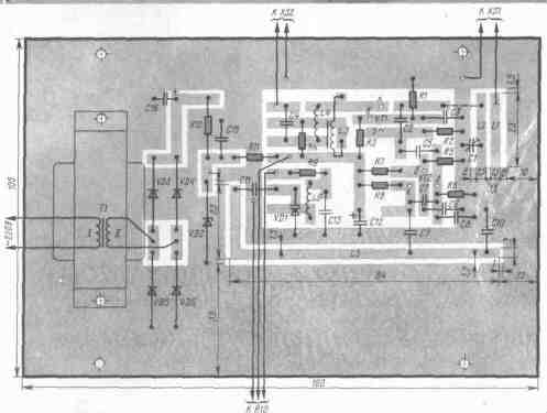
Fig.2
The fee is placed in a plastic housing dimensions HH mm from a sheet of vinyl plastic with a thickness of 2 mm (acceptable use and metal). It can be installed h inside the TV, having fixed variable resistor R10 on the case. In this case, the wires connecting the resistor with the Board, placed in a shielding braid, and a capacitor C14 is brazed to its conclusions.
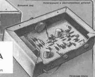
Fig.3
Console build with weak TV signals (for example, when the power of the antenna) for maximum image contrast. If you intend to take a few programs, the input circuit L2C1 set by capacitor C1 to the high-frequency channel. The output circuit is set by changing the inductance of the coil L4 (found in the position podstroechnik fixed microcrystalline wax or stearin).
Author: N. Katrice, Khmelnitskiy; Publication: N. Bolshakov, rf.atnn.ru