


")

The ability to connect multiple external sources (VCR, video player, camcorder, video player, etc.) to modern TV's are very important to their function. About video switches and audio transistors have already been published in our magazine. Here the author offers a description of the structures on chips that can use in both new and older vehicles.
A switch that allows you to connect to the TV, external sources of video and audio signals. - a necessary component to any modern TV.
In domestic equipment such devices are used, starting with the second generation of color TVs. In the receivers OPENCT. for example, the on-Board unit signal processing (BOS) is provided for the fitting of MIND module 1-5. providing interface VCR (VM) with TV. Such a module mounted on the plug connector (if it is not. it is set) with seven contacts. In module uses ten transistors. His scheme is considered in[1].
Module UM1 -5 operates in two modes: playback programs and videotapes the entry for essential programs. It has a two-wire input / output and is designed for use with VM, also with a common socket input / output signals. It circumstance complicates application of new VM models, whose inputs and the outputs are separate. Connection modupe to videoplayer, seemingly no difficulty is not. But the power module and the regimen playback available only from the VM. while modern machines no produce the necessary voltages, to apply the MIND 1-5 without the modifications to this equipment.
The Loewe ZUSTST used the same module MIND 1-5 subjected a small upgrade. In it there is another transistor, connector for install the module in charge MRK has ten contacts. Schematic diagram this version of MIND module 1 -5 published in [2]. System power and control modes of operation has not changed, and disadvantages remain the same.
Industry produced another version of this module under the same name. This the model differed from the former, designed for TVs ZUSTST. the. what received the power is not from the VM and from the TV. The control module continues to descended from WM. This model is used in the fourth generation TVs "Ruby - TS/4103/4105". Her scheme described in [3].
In TVs SELENA-CTV441, TVT441. HORIZON-STU applied module coordination with external devices WM-45. where previously named the disadvantages are eliminated. The module contains five transistors. In the TV HORIZON-CTV510 applied for that purpose module ICC-501 on five transistors and two chips. Schematic diagrams of these two modules considered in [4].
Similar devices for TVs of different designs, starting from WPCT. offer at radio. Great interest in their creation and show ham radio operators. Many of them have developed such devices mainly transistors and relays. The last version of this switch was described in [5].
In TVs the fifth and next-generation switches video and audio signals implement already. typically, in integrated execution. They used specialized chip, and in some cases (e.g. on TV chips TDA8360-TDA8362 and their analogues) switches incorporated into the structure chips themselves.
The benefits of using ICS is obvious. They allow you to simplify the design of the switch signals, get rid of the mechanical devices to improve the interchange of inputs and outputs. Today there is a ham radio there are many chips that can switch signals from any number sources. The voltage is different and their is usually in the range from 5 to 15 Q. let's analyze those. powered 12 V available in all domestic television sets.
In the apparatus ZUSTST easiest option switch video and audio signals for two sources (e.g., from radio to TV and from VMS) can be the device, built on a chip TEA company SGS-THOMSON. His scheme it is shown in Fig. 1. DA1 chip has three electronic switch, switching video (S1) and audio (S2) signals. Switch S3 in position AV connects pin 7 of the connector XS (A1) - change t Epcip - a common wire.
(click to enlarge)
Video and audio signals from the radio module (MRK) on the TV via the contacts 1 and 5 connector XS (A1) are on pins 3 and 8 of the chip DA1. The same signals from an external source is received on pins 14 and 7 of the chip. With pins 12 and 6 video and audio signals come on the contacts 4 and 2 of the connector XS (A1), and with them in the MRC. Switch the signal sources, the switch SA1. To enable essential program (TV) you need to apply +12V to pin 10 of the chip and connect conclusion 11 the common wire. To enable an external source (AV) voltage of 12 V served on the pin 11 and connect pin 10 to GND.
When you switch to the AV mode is necessary to provide a switching device Epcip lowercase in sweep mode with a wide swath. This is achieved by connecting the pin 7 of connector XS (1) General wire inside the chip when it pin 10 is connected to a common wire when installing the SA1 toggle-switch to "AV".
The pin assignment of plug and socket connector XS (A1) in Fig. 1 shows differently. On the plug it corresponds to the original scheme MRK. considered in [2]. and on the outlet - purpose circuits in the switch.
Charge switch connected to the plug connector XS on the Board of MRK radio, intended for the MIND module 1-5. If this plug is not, it should set in the sockets provided for her.
When using the switch in the MRC TV ZUSTST you need to make the changes shown in Fig. 1: remove portions of the circuits shown dashed lines, and install new circuit drawn with thick lines.
The essence of the alteration consists in the following. In the original scheme of the video signal from MRK o 7 submodule SMRC-2 runs parallel to the pin 1 of the connector XS, in block FCP through contact 1 of connector X8 (1.4) and the modulus of color through contact 1 connector X6 (A2). Under the new scheme the connection SMRC-2 and XS connector retain and connectors X8 (A1.4) and X6 (A2) the signal after switching in the switch through pin 4 of connector XS.
Audio output 23 SMRC-2 came to the resistor R6. Now it needs be held in the switch on pin 5 of the connector XS (1), and the resistor R6 with a signal from the output of the switch (pin 2 of the connector XS).
When using the MIND module 1-5 in playback mode signal VM at the TV from the module receives a command to lock UPCI and UPCS. Changing the chains of transmission video and audio signals eliminates the lock and allows you to submit essential a program from the TV to the VM constantly. So pin 6 of connector XS (A1) leave free.
Switch to two sources, the appearance of which is shown in Fig. 2, assembled on the Board of two-sided foil fiberglass with a thickness of 1.5 mm. the drawing and placement of the parts on it are presented in Fig. 3. Printed the wires from pin 7 of connector XS (A1) to pin 5 of the chip and or DA1 capacitor C6 to pin 8 held on the Board with side parts (shown dashed green lines). The arrow on the connector H is metal limiters installed to ensure proper connection.
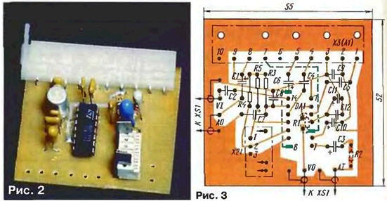
Resistors R1 and R2 - chip components size 1206 or 0805, others with MLT a tolerance of ±10 %. The capacitor C11 - C50-35 oxide or any small-sized. C1. C3. Sat. C7. C10 - any type tantalum, other - K10-17. The XS connector (A1) - socket with ten contacts, H socket with six contacts.
In Fig. 4 shows a schematic diagram of the switch signals for the three sources: TV, AV1, AV2 where AV1 - VM with separate inputs and outputs, a AV2 - video device not having the function of recording signals (video player, games console, laserdisc player).
The switch is assembled on two chips TAR TOSHIBA intended to switch both video and audio signals. His scheme has not fundamental differences from those shown in Fig. 1, and it requires the same modifications in the MRC of the TV. Changed only the control circuit and signal conditioning "Am. t Epcip". To switch the source of the signals applied to switches: SA1 with the provisions of the "TV" and "AV and SA2 with the provisions of the MAV1" and "AV2". Signal "CH. t Epcip" (it must be equal To 0 in modes AV1, AV2) is supplied to pin 7 of the connector XS (A1) with the pin 1 of the connector H.
The switch to three sources, the appearance of which is shown in Fig. 5, collect on the same circuit Board as described above.
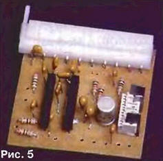
A drawing of PCB and the placement of the parts on it are shown in Fig. 6.
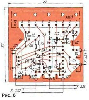
The resistors R1, R3 - chip components, the rest of the IFL with a tolerance of ±10%. The capacitor C12 - oxide. C2, C7-C10 - tantalum. the rest - K10-17.
In the switches used chip components, still rarely used in Amateur radio practice. The resistors, capacitors, coils, diodes and transistors were miniaturized. Chip resistors and capacitors perform in the form of the rectangular enclosures in standard sizes. Buildings have digital designation: 0603, 0805,1206,1210,1808, etc. the First two digits indicate the length housing in hundredths of an inch, the latter its width. The most common and convenient for mounting the housings 1206 and 0805. Chip resistor case 1206 has a length of 0.12 inch (3.2 mm) and a width of 0.06 inch (1.6 mm) with a height of about 1 mm.
The chip components come from the manufacturer Packed in an individual cell paper tape and to installation shall be stored in this packaging. More detailed information about the specifics of their installation, inspection and dismantling can be found in [6].
The chip components are mounted on the pads with the dimensions shown in Fig. 7. In the fractional size of the numerator means the amount for the housing 1206, the denominator for 0805. All dimensions are in millimeters.
To mount the chips is recommended in the following order. Mounting pad (tinned), soldering paste, and they make the chip. Due to the viscosity paste this virtually weightless body to be secured in the right place at the soldering process. Then the chip is placed more accurately and fixed on the soldering time narrow screwdriver, wooden stick. Interestingly, chip resistor, unlike other the chip parts is attracted to a metal screwdriver, which is usually magnetized.
The edges of the chip is metallized with Nickel and top of the tin (or solder). Metallization captures narrow strips on the top and bottom of the Cabinet at ends. Solder the chip. using solder POS-61. The power of the soldering iron with a sharp the sting should be no more than 30 watts. Due to the small distance between mounting the sites and their proximity to nearby printed lines may appear unwanted jumpers. Their absence is checked with an ohmmeter. When working with chips it is recommended to use a magnifying glass.
It should be borne in mind the characteristic feature of the chip components. During installation due to vibrations in the air they can at any time be wasted. Why the need to be special care when removing them from the packaging, the installation on site, in the initial time of soldering, etc.
ri wanted to have the switch on four or five inputs should to use and the appropriate chip for example. BA7644AN. VIA company ROHM can switch between four inputs and VIA the same company - five. For switching the audio inputs you will need two chips CAR included consistently. To the inputs of one of them connect the three source signals, and to the other inputs - the output of the first circuit and other sources. Management switching, of course, is more complicated, but the diagram is not difficult to do with the the options considered in Fig. 1 and 4 in the first part of the article.
External framing (mounted parts) chip and method of forming signal CH. τ Epcip" may be a similar option for three sources (see Fig. 4) with amendment to the other chip Pinout. Their structural diagrams and pinouts available in [7].
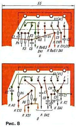
Switches, circuits which are represented in Fig. 1 and 4. you can apply in TVs OPENCT. In them (as already mentioned) establish semicontact variant of MIND module 1-5. To connect addressed switch outlet XS (A1) that they should have seven contacts, which requires changes in a printed circuit Board. They are depicted in Fig. 8,and - for the first option switch and in Fig. 8,b for the second one. Chains that do not undergo change depicted red, new green.
Changes to Board barefoot, is required when using any option switch shown in Fig. 9.
All of the above applies to TVs with push-button devices select programs USU-1-15 and MRAs (SWП. Profit center) of any type. Switching of operating modes and sources of signals in them is provided by toggle switches mounted on the front of the TV or in any other convenient place.
If your TV is set to the voltage synthesizer the sit-405 (or the sit-501), to manage the switch signals is possible through him.
Managing the switch by the circuit of Fig. 1 signal is provided by the AV/TV, generated on pin 12 of connector x2 (A1) synthesizer the sit-405 (or on the withdrawal 8 connector X7 (A1) in the sit-501). In the sit-405 it occurs when pressing buttons VCR on the remote control or the keypad on the front panel of the TV. In the sit-501 click on button AV or TV on the remote control.
To implement this method of control in the switch in the circuit in Fig. 1 you need to make the changes according to Fig. 10.
The SA1 toggle-switch, resistors R4 and R5 is not need. On Board are installed in a free space on the transistor VT1 and the resistor R21. R22. In the case of the use of the synthesizer of the sit-405 will also be required to achieve the required level voltage at pin 32 of the microcontroller, follow the guidance in section iaai Handbook [8].
If use the switch signals of the three sources, it is possible to manage them requires two signals: AV/TV and AV1/AV2. In the sit-501 first of them, as has been it is written, remove from pin 8 of connector X7 (A1) synthesizer, and as second - will suit a switching signal broadcast standards PAL or SECAM - conclusions 12 or 15 connector X10 (A1 synthesizer. This signal when the unit is installed The sit-501 in TV ZUSTST not needed, and the conclusions remain free. The signal AV/TV is formed by pressing AV / TV on the remote control. Signal AV1/AV2 occurs when you the SS button on the keyboard synthesizer. Connection scheme of the sit with switch signals shown in Fig. 11,and. The switches SA1, SA2, resistors R5 and R6 and the diode VD1 't need.
Note that there are several modifications of this synthesizer manufactured various enterprises. They have some differences. So, in the synthesizer The sit-503 (similar to the sit-501) and some models of sit-501 SS button (switch standards) replaced with button CL (clear memory). In this case, for forming signal AV1/AV2 will have to install a toggle switch.
In some models the sit-501 signals PAL, SECAM with the pins of the microcontroller are not come on connector X10 (A1). To address this deficiency need connect the output 38 of the microcontroller with DD2 pin 15 of connector X10 (1) through the circuit shown in Fig. 11, b.
As for the synthesizer of the sit-405, then applied it to the microcontroller SAA1293A has a pin 25 on which is formed the signal selection standard color. However to use it, since on the remote control and the keyboard synthesizer no buttons operation of this function. You have to switch AV1/AV2 use external toggle switch.
All mentioned in the article chips are shopping directories firms with the price 0.4 to 1 USD.
The switch, assembled from proven parts, and does not require adjustment after check for short circuit in the power supply +12 it can be installed in the TV. Performance check a toggle switch (the buttons on the remote control and keyboard).
You should also make sure that the TV mode on pin 7 of connector XS (A1) receives voltage 5… 11 V, and AV mode it is equal to zero. Current consumption on circuit 12V - about 35 mA at the switch by the circuit of Fig. 1 and about 27 mA - switch by the circuit of Fig. 4.
Literature
Author: V. Brylov, Moscow