The problem of distribution of the signals from their sources to multiple consumers recently often confronts users of video and audio equipment. For improve playback quality published author of the article suggests to do it's at a low frequency, separately for video and audio signals.
Sources and consumers of video and audio signals in apartments, Russians more and more. It - TVs, VCRs, satellite receivers, camcorders, music players, etc. Some of them traditionally connect a high frequency (radio frequency). The signals from VCRs and receivers (usually in the UHF range) is transmitted to the TV via a coaxial cable. When the presence in the apartment two or three TV signals have to share and pass on at distances up to several tens of meters, resulting in a significant the weakening. In addition, it is necessary to apply additional RF amplifiers. Plus not every cable is suitable for transmission of signals in the UHF range.
Arises such a problem as a multi-feed signals to the TV if it has one antenna input, so you need to use the adders. Often appear mutual interference between the radio signals of broadcast television stations and a radio signal from a VCR or receiver that degrades the quality of reception as those, and others.
In such cases it is advisable to send separate video and audio signals a low frequency that will ensure a higher quality playback, though this will require two shielded cable. However, they can be very cheap, since the signals are transmitted at relatively low frequencies. Besides single conductor (for audio) can be newassociations, quite quite a regular MIC cable.
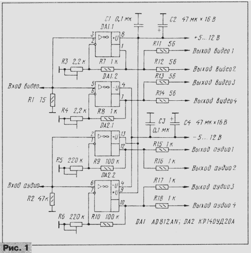
When a source separate video and audio signals only one, and consumers a few needed a splitter, which is offered to collect themselves radio Amateurs. Its schematic diagram is depicted in Fig. 1. It is executed on two chips. One of them (DA1) - high speed (1600 V/µs) dual powerful OS AD812A. Its distinctive options - broad band amplified frequencies (100 MHz), linear phase response, output a current of 50 mA and relatively low cost (3...4 dollars). Such parameters provide a video signal amplifier which is in good agreement with coaxial cable and is able to simultaneously work on two or three of the consumer. The total number of consumers can be up to six (three for each channel).

From source video signal is fed to the "Input video", to which to reconcile connected resistor R1 (the value is equal to the characteristic impedance of the connecting coaxial cable). The signal comes simultaneously on two channels amplifier, and each of them a trimming resistor (R3 or R4) can to obtain the desired transmission rate. Such a construction allows individually to establish the most suitable level of the video signal for each consumer. Response of both channels of the amplifier is linear up to a frequency of 10 MHz.
The path gain of the audio signals collected in a similar way to dual op amp CRUD.The transmission coefficient in each channel is also established a trimming resistor (R5 or R6). Response of both channels of the amplifier CB linear to 20 kHz.
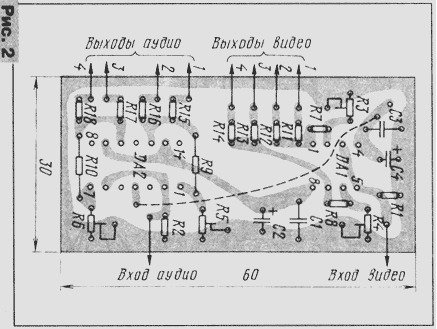
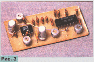
All parts of the instrument are placed on the PCB of unilateral foil fiberglass. Drawing printed conductors on the Board presented on Fig. 2. The appearance of the splitter shown in Fig. 3.

The device is AD812A possible to use chips AD817A, AD818A (with changing the PCB). However, they are less rapid and also single-channel. Is advisable to use where the number of consumers is not exceed three. Also suitable chip AD813A having three Oh in the housing (but the circuit Board also needs to change).
Trimming resistors in the device - small-CP3-19a, and when the fees and other, larger. The remaining resistors - MLT, S2-33 (all of them, except R9 and R10, is mounted perpendicular to the Board). Capacitors C1, C3 - km, KLS, K10-77, and C2, C4 - oxide K50-35 or similar.
To power the device applies the bipolar stabilized power supply with output voltages from 5 to 15 V. the Current consumption with no load, approximately 15 mA, and under load it rises to 70...100 mA.

Starting to build a splitter, you need to install the sliders all trimming resistors to the left in the diagram position, and then when connected consumers, using resistors, to achieve the most appropriate level signals.
The number of outputs can be increased to six. To do this for each OS optionally, connect a resistor of that denomination: 56 Om - amplifier, 1 Ohm - amplifier for audio signals.
Author: I. Nechaev


