


")

In the basic set top box, referred to, designed for connect to the composite video input of the TV. However, on the TV screen, having a socket SCART or S-video input, it is able to create the image of much higher quality, you need only the appropriate connection cable. Unfortunately, in the sale of such cables do not. Unlikely to purchase and necessary for their self-made cable plug, motivated by the socket "AV OUT" the top box. It remains to redo the cable, included in the set top box. With the plugs removed plastic case, pre cut it with a knife along the side seam. Tilting the metal edge of the screen, remove the terminal block with contacts.
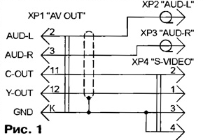
Pin 1 is removed from the pads, soldered to it center conductor shielded wire (of length equal to the length of the cable) and establish contact in available slot pads designed to contact 11. Pin 13 is transferred in the socket contact 12. Assemble the connector, do not forget to connect the braid added wire screen with a fork.
It remains to be determined at the opposite end of the cable according to the scheme shown in Fig. 1, plug 2, HRS (RP-405 RCA, known as the "Tulip") and HR (mini-DIN-4M).
At radio sometimes you can find cable assembled according to the scheme depicted in Fig. 2. On assurances of sellers it is designed to connect a video game console "Dreamcast" with the RGB inputs on the TV. However, the cable has multiple errors not allowing it to be used for the stated purpose.
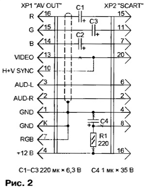
To switch the set-top box in the generating mode for RGB signals, pin 7 plugs HR need to connect a common wire. And that in RGB mode on the top box the TV did sync with the contact 20 of the plug 2 to be connected by the the contact 10 and not 13 fork JR.
To switch the TV to receive the RGB signals to the socket 16 of its connector SCART (which dock plug XP2) serves voltage of +12 V. According to the plan manufacturers of cable it is supplied through the resistor R1 with the slots 8 of the same connector. Unfortunately, not all TVs need a voltage there. Even if it is, this method of switching is extremely inconvenient, because for view normal TV shows have to be necessarily disconnected from the TV cable top box.
To eliminate defects, to make the purchased cable additions and changes, it is shown in Fig. 2 color. Necessary loose contact in the block fork JR available. The resistor R1 and the useless, the capacitor C4 is removed.
Often the only SCART socket on the TV have to connect it a top box, VCR. To avoid multiple re-docking connectors help the device is assembled according to the scheme shown in Fig. 3.
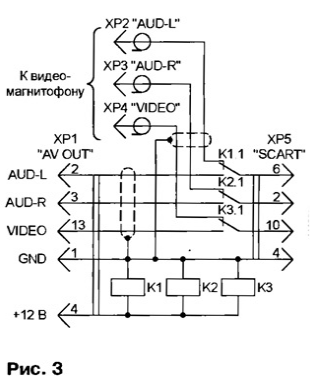
When turned off the video game console, the voltage on the windings of relays K1 - K3 is zero, the anchor is released, the TV connected to the VCR. When the prefix include, winding on relay contact 4 of the connector HR supplied voltage of 12 V. The contacts of relay triggered off the audio and video inputs of your TV from VCR and connect them to the console.
Small relays RAS (performances RS4.569.421-02 or RS4.569.421-08) and they such can be placed in the plug HR. A reserve power source voltage 12 In the top box for the relay supply is quite sufficient.
Author: P. Lyubimov, Bobruisk, Belarus