In many models of modern TV sets applied to the channel selectors with electronic tuning IC-IN-1S. SC-B-2C, SC-M-e, SC-M-23 and SC-D-22. The varactors of these selectors is supplied a DC voltage is in the range from 0 to 25...28 V (depending on the channel number). These TVs are relatively easy to make a panoramic view of the television bands and setting the panorama to the desired channel. To do this, from the sawtooth voltage from the unit frame scanning, it is necessary to generate the voltage required form, varying from 0 to 25...28 In, and submit it to the varactors of the channel selector.
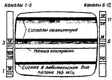
As a result, the setting of the selector in any of the subbands is changed from the upper to the lower frequency with a refresh rate of the TV. Consequently, the brightness of the screen of the kinescope, of the beam from top to bottom, depends on the presence of signals of television transmitters operating in the selected band. On the screen are formed by the dark horizontal stripes, the width of which is proportional to the bandwidth of the if amplifier image (UPCI) to the TV. In Fig. 1 for example shows a panorama of the received signals in the high frequency sub-band (6-12 th channels) meter waves observed in Moscow at the TV "electronics-450". And quite noticeable difference between image signals and sound. The band of image signals (of.) lighter than sound signals (SV.).
To setup the TV with a panoramic view it is necessary to obtain visible on the screen tag corresponding to the voltage settings, adjustable available in the TV authorities. With this purpose, compare the tuning voltage with a sawtooth voltage applied to the varactors, and form the desired waveform. Label settings is displayed on the TV screen with strips from operating transmitters and different from them in shape and brightness: it's a thin white line, shown in phantom in Fig. 1 black.

Fig.1
Panoramic view to setting appropriate to apply in TVs with touch switch channels, which scales the settings on the front panel there, and available at the touch switches of the scale are small and uncomfortable to use. Sweep panorama allows you to equip a convenient TV and a large tuning dial, the length of which is equal to the height of the screen. The boundaries of received channels for each sub-band can be applied to the side edges of the frame of the screen.
In Fig. 1 shows a layout example of the scale of the low-frequency (1 to 5 channels) and high frequency (6 - 12th channels) sub-bands metre waves for panoramas observed in Moscow at the TV "electronics-450" (the channel selector SC-M-e). In the television channel selectors SC-In-1 pan and scale high-frequency sub-band (6-12 th channels) will be the same. Near this scale can accommodate the scale of the range of decimeter waves, and instead of one scale sub-band 1-5-th will be two channels: on the 1-2 and 3-5.
After switching the TV on / off sweep panorama and touch settings switch used for switching ranges, and available in the switch variable resistors to tune to the desired program.
The TV comes with a panoramic view do not need to blindly switch all sensors in a row in search of working transmitters, and immediately you can enable the desired program. For this next to the scale between the borders of channels attached to the mobile tag with the numbers of programs. In addition, on such large scales can even fine-tune the TV to this channel. Indication accuracy is high due to the fact. what the label settings can be done is many times thinner than the width of the stripes from the transmitters.
Conveniently panoramic overview and setup to use for the coverage area where the signal received television transmitters has an irregular character. On the TV shows in which part of the sub-band passing has improved, and where signals are weak. After that, you can include the desired channel with a strong signal. And finally, a panoramic view can more successfully be used when establishing and orientation of antennas in interference from TV transmitters operating on adjacent channels, and from other sources. The antenna is oriented, achieving the disappearance of the marks from interference sources and the clearest display of the bands of the received signals of TV transmitters. The video showed what part of the sub-band noise is most intense, and can even determine their frequency.
You should know that the capacitance of the varactors used in channel selectors with electronic tuning, depending on the applied voltage, linearly, i.e. small voltages correspond to large values of capacity and rapid change, and great contrast. Therefore, if the varactors submit linearly varying sawtooth voltage, the screen of the TV bands from transmitters operating in the low-frequency part of the sub-bands will be condensed, and in a high-frequency - sparse. To strip on screen was located uniformly, the voltage applied to the varactors must be non-linear for small values should change more slowly, and at large - faster. To this end increasing sawtooth voltage taken from the frame scanning unit, it is necessary to increase the amplitude of 25...28 V and invert it, turning it into falling to then, differentiating, to obtain the necessary nature of change in voltage.
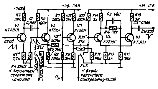
Schematic diagram of the node that generates the desired sawtooth voltage and the signal of the label shown in Fig. 2. Personnel sawtooth voltage is amplified and inverted by the cascade transistor V1 and is differentiated by the circuit C1R3R4. In the cascade transistor V2, assembled by an emitter follower, the voltage is limited to and through the switch S1.1 is supplied to the varactors of the channel selector. The repeater is powered by the stabilized voltage supplied to the TV to the variable resistors settings. Therefore, the voltage at the emitter of the transistor V2 can not be more than 28 To 30, which eliminates the possibility of breakdown of the varactors. Switch SI on the varactors can be served either previous voltage settings (in the "Program"), adjustable variable resistors in the TV, or generated voltage (in the "Overview").

Fig.2
The sawtooth voltage across the resistor R6 affects the Schmitt trigger transistors V4 and V5. The trigger through a resistor R10 to the output of the inverter transistor V3 also comes voltage settings. When the trigger fires regulation at different levels of the sawtooth voltage. As a result at the output node after the condenser C3 form a narrow pulse which is supplied to the amplifier and forms on the screen of the kinescope label settings. The Switch S1.2 in the "Program" closes input trigger and eliminates the appearance of marks on the taken image. In browse mode and configure the switch S1.2 closes the input selector clock on the TV. This eliminates synchronization oscillator sweep of the various pulses generated at the output of the radio when you hit the bandwidth of UPCI all possible carrier frequencies with a panoramic overview of the sub-bands. This removes the bumps and curves of the vertical raster boundaries that hinder the observation of bands from TV transmitters.
When connecting a node to TVs electronics-450" increasing sawtooth voltage to the base of transistor V1 can be removed from the output of HR coils of the deflection system not connected to the common wire. The contacts of the switch S1.1, attached to the TV circuits consist of a broken wire going to the engine variable resistor configuration R2 TV (the fixed contact to resistor). The contact of switch S1.2, connected to your TV, combined with the withdrawal of the base of the transistor T8 of the block A2, and the output capacitor C3 is the output of the emitter of the transistor T4 of the output stage amplifier. Voltage 28 To 30 fail with the Zener diode D4 unit A3, and a voltage of 70 In - contact with 14 of the same block of the TV.
In TVs electronics TS-430" sawtooth voltage is removed from the output collector of the transistor T9 of the module frame scanning, wherein the resistor R1 of the node is disconnected from the common wire and connect with a point, which receives voltage - 12 V supply of the module. The Switch S1.1 include a gap in the connecting wire between pin 13 of the channel selector with the socket 10 of the connector x2 of the block A5 in the TV. The contact of switch S1.2 is connected to the base of transistor T2 of the module frame scanning, and the output node with output 3 circuits D1, D2 or D3 (depending on the desired color of the label) module A7. Voltage 28 To 30 can be submitted with the socket 10 of the connector X1 PSU.
The sawtooth voltage in the TV series UPITT-32-d get with contact 4 of the connector 2X2 module frame scanning. The contacts of the switch S1.1 site include the gap in the wires connecting the connector socket 2 GB socket 9 connector HB (the latter is connected to a movable contact of the switch). The contact of switch S1.2 is connected to the base of transistor T2 module MZ-1 (AR3), and the output node to the output emitter of the transistor T3 module A9 motorway, And 10 or A11. Voltage 28 To 30 off of the Zener diode D1 M5 Board-3 block range of programs.
Finally, the Loewe OPENCT-61-AND increasing sawtooth voltage gain of the output from the emitter of the transistor T8 of the module frame scanning. The contacts of the switch S1.1 site include a gap in the links connecting the pins 8 boards presets and block MRAs (pin 8 of the latter is connected to a movable contact of the switch). The contact of switch S1.2 connects to pin 7 of the module MZ-1 (AR1), a output node to the output emitter of the transistor T3 module A9, 10 and A11 (depending on the desired color of the label). Voltage 28 To 30 is removed from the pin 5 of connector W-P2 unit SVP.
In TVs electronics TS-430", as well as series OPENCT-61-II, and UPITT-32-IV voltage 70 To receive additional stabilizer Zener diode X or DB, giving him one of voltages of 220, 190, 150 or 120 available on these TVs, via a resistor 16 ohms and a power dissipation of 2 watts. Voltage 10...12 formed in the power supply all the TVs, removed from any convenient point.
The parts of the unit can be placed, as made by the author, motherboard parts used in computer devices for mounting integrated circuits. The scheme of connection of details to sites such fees and connection between them is shown in Fig. 3.
When establishing the first node, selecting resistor R1, to ensure that the amplitude of the sawtooth voltage on the base of transistor V2 reached 25...28 V. Then in browse mode selection resistor R6 "stack" the boundaries of the study sub-bands in the borders of the image on the TV screen. Resistors R10 and R13 affect the coincidence of the label settings with stripes from television transmitters. Therefore, aligning the mark settings with a strip from the transmitter, set switch S1 to position "Programs" and make sure in the normal image pickup and the sound of the selected program. If reception is not there, then choose these resistors. Selection of the resistor R10 has a greater effect on the boundaries of moving markers at high frequency, and the resistor R13 is in the lower frequency channels.
Good reception of image and sound is supposed to be in the position of the label settings about low-frequency border of the strip from a TV transmitter. Selecting the capacitor C3, you can change the pulse duration and, consequently, the thickness of the label settings on the TV screen.
Author: C. Sotnikov, Moscow; Publication: N. Bolshakov, rf.atnn.ru


