


")

Described here is the module channel (ISC), the appearance of the PCB which is shown on the 1st S. the cover of the magazine "Radio" No. 1 this year, aims to replace the module MRK-2 in TVs USCT. It has a relatively small size, small number of interconnect, lower power consumption and improved performance of systems horizontal and vertical synchronization. Application import channel selector allowed to exclude two blocks SC-M-24 and SC-D-24, to provide a combination of antenna inputs MB and DM In, obtaining a high rate amplification and reception of cable sub-bands. In addition, the opportunity use to control the TV synth module voltage of the sit-501-9. The disadvantages include the inability to work in standard B/G (but Russia it is not used).
System horizontal sync used in the MRC chip TDA8304 excludes noise on the screen when a weak input signals and noise, as well as the appearance dark stripes on the edges of the image. In the system of vertical sweep circuits improved temperature stability of the parameters of the HR signal, as a result received the best deinterlaced image. Much less dependent parameters systems and of the supply voltage.
Learn more about the work and the functional nodes of the chip described in [1].
When developing for MRK was based on a schematic diagram of the TV "Horizon 54CTV601" [1], which used the chip TDA4504B. Note that chip TDA8304 different from TDA4504B only improved characteristics.
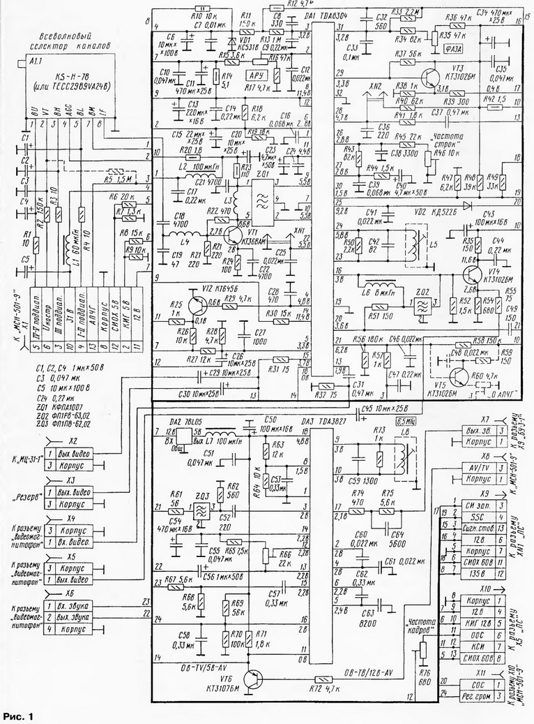
Schematic diagram of the MRC is shown in Fig. 1.
(click to enlarge)
The received radio signal is amplified and converted to an if signal 38,9 MHz a channel selector A1.1. With its release, the IF signal passes through a matching the amplifier transistor VT1 to the filter surfactant ZQ1. With its symmetrical output the signal is fed to the processor of the radio channel (pins 9 and 10 of the chip DA1). In chip it is amplified and detected. With its output 20 video input (with AC drive sound 6.5 MHz) arrives for the notch filter ZQ2, where the if signal sound suppressed. As a result, the base of transistor VT4 and the pin 16 of the chip there is a full color television video signal (PCTV).
From the output of the emitter follower transistor VT4 video signal is supplied to connector X5 which is connected to the video input of the VCR. At the same time the video comes to internal switch (pin 16) of the chip DA1. "AV/TV" TVs manages the key on the transistor VT6: low voltage (B) on the emitter of the transistor includes an internal signal (TV), high (5 V) - external signal (AV). Control voltage affects the output 18 of the chip DA1 and the output 11 of the chip DA3 (the latter is used for switch management sound).
The external video signal is served on connector X4 and the output and input signals of the sound - on connector X6, which connect a VCR.
The video signal after switching via pin 15 of the chip DA1 and chain R31C29 passes through connector x2 on module chroma (MC-31-1). Connector XS - backup.
From the output 20 of a chip of DA1, the video signal containing the if sound, through the chain of C49R61 comes to bandpass filter ZQ3 that selects the if signal sound 6.5 MHz, input via pin 3 of chip on DA3 sound demodulator. Further sound processing is going on in that chip.
From the output of the adjustable amplifier through pin 17 of the chip DA3, chain and R74R75C64 connector X7 the 3H signal passes to the amplifier in the unit BU-3-1. Adjustment volume control is achieved by varying the DC voltage at pin 16 chip DA3. It comes on pin 3 of connector X11 block from the sit-501-9. Initial voltage set by divider R69R70.
All of the elements and circuits of each of the pins and nodes to describe not will. We will consider here only the connection features of the sync outputs frame and line scan, and the feedback circuits and the Gating signal (SSC).
Flyback pulses start with amplitude equal to 0.8… 1 In, are formed on the output 29 chip DA1. After passing through the emitter follower transistor VT3, they received through pin 3 of connector X9 on the module line scan MS-1. Chain connect the same way as in [2].
For reasons discussed in [2] (different shape and amplitude), pulse control output stage vertical fed through the amplifier-inverter on the transistor VT2. With its manifold human pulse amplitude of 10 11 In… come through pin 7 of connector X10 on the frame scanning module MK-1-1.
As for the EP, it is applied without protective properties, described in [2]. The divider R27R28 in MRK installed to restore the DC component in chain EP and unlock the nodes scan the inside of a chip of DA1. Capacitor C26 is used to pass a sawtooth component and prevent shunting of the divider circuits of the module frame scanning. A trimming resistor R76 regulate the level of staffing sawtooth waveform, and therefore, the frame frequency. The resistor R14 in the module MK-1-1 this function is not performs.
The Gating pulses SSC via the output 30 of the processor DA1 and pin 4 of connector come to the chroma module. The divider R47R49 reduces the level of lowercase the flyback pulses of 60 V to 5 V for the formation of pulses superstropharia SSC. The divider R47R48 is to obtain the necessary DC component these impulses.
As for the circuit current limitation rays (EX), in TVs when USCT the current rise of the tube voltage in the circuit increases, and the TV CTV-601, on the contrary, decreases. However, in TVs USCT there is a circuit in which the voltage also decreases proportional to the current of the kinescope. This is the circuit "Signal stabilization". To her and need to connect the wire EX.
In the MRC applied trimming resistors SDR-38. The remaining resistors - any (suitable for the size). Capacitor C38 - K71 -7 with a tolerance of 1 % for voltage 250 In (required highly stable), C7 - K73-17 a voltage lower than V. 63 Other import compact. Chokes - PDM, SCM.
Coils L3-L5, L8, filter ZQ1 taken from submodule SMRK-1-5. Filters ZQ2, ZQ3 - FPR-63,02, PPP-62,02 accordingly, also in SMRK-1-5, but the fit and imported.
Transistor KTA (VT1) to replace KTM, CHAM, CTB (VT2) - CTA, CTM (VT3-VT5) - KT3102 with any other letter, KTM (VT6) - CT also with any letter index. Instead of chips you can install TDA8304 TDA4504B, CRHA, instead TDA3827 - CRHA, and instead of the stabilizer (+5) 78L05 - CREA, but the fit and CREA.
To know the characteristics and choose the channel selector will help the article in [4].
When you install a new RTOS should introduce some changes to the blocks MC-31-1,BU-3-1, PS and the sit-501 -9 TV.
It would be better to install the TV module of the sit-501, but its author was not, therefore, the following describes modifications of the module of the sit-501-9. Anyone can to connect to IRC as the sit-501, and staff, USU-1-15. In the latter case you need to add a resistor R5, shown by a dotted line, and adjust how to solder the connectors. Elements R59, R60, VT5, C48, also shown by a dotted line, establish in the case of podsterech Board the resistor R22 in the block sit no access. Adjustment "ON APCH" this do in the MRC unit, placing these elements and removing the resistor R57.
Scheme of connection cables leading to the module MRK blocks from the TV, and from MRC to the Board connections of the substation shown in Fig. 2.
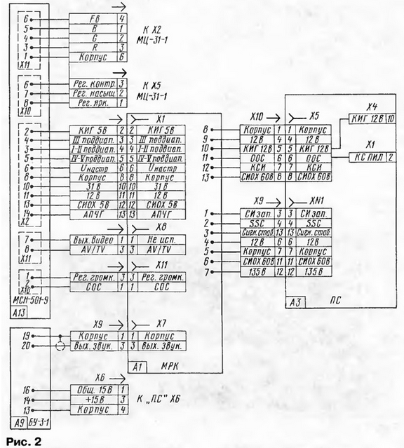
On-Board PS in available holes for pins 5 and 6 of connector X5 insert probes and, solder them insulated wires, connect them with the pin 10 of connector X4 and pin 2 of connector X1 Board, respectively.
In the same way as in [5], all connecting the wiring going from the sit module-501-9, fed, lengthen and raspalaut according to the scheme in Fig. 2. In the block The sit-501-9 [6] removes the elements of R75, R76, R83-R85, VD1, VD14, VD15, VD17, VT17, VT18, VT20, diode VD4 replace the bridge, and the resistors R43 (56 ohms) and R42 (47 com) are replaced with the values of 510 and 620 ohms respectively.
In module chroma MC-31-1 [3] you should remove the elements VD1, R32, and instead resistor R31 to install a jumper. When using blocks of sit-501 and the sit-501-9 resistors R4-R6 in the module chromaticity replace the jumpers. In block BU-3-1 [3] remove elements R23, R22, VD1, C10 (in the case of CCA-1-15 need them to leave).
After Assembly of the module and check for shorts and errors in the installation paste it instead of the MRK-2 and connect all connectors according to the scheme in Fig. 2. Before the inclusion of the TV all engines rigged resistors to set in the middle position. The same applies to a setup resistor R22 in the block The sit-501-9. The trimmers coils L5, L8 in MRK screwed to the coil L5 podstroechnik performed relative to the shear frame for about 3…4 mm, and in the coil L8 - 1…2 mm.
After turning on the TV raster should appear. In his absence check voltage 12 and 135 (130) To the outputs of the power module. In the case of normal values measure the voltage (about 3.3 V) on pin 5 of the chip DA1 MRK. If it is not, check the items R27, R28, C26, and the presence of voltage at 12V contact 4 of connector X5 PS Board.
When the glow raster pre-set the number of rows and frames trimmer resistors R46 and R76, respectively. In the power module MP-1 (MP-3-3) exhibit trimmer output voltage 135 (130) and 12 V.
If you have an RF generator and oscilloscope, establishing spend as it is stated in [1, p. 308]. It should be borne in mind that the reference designators the adjusting elements in the MRC is different and will have them to compare with similar features in the TV CTV-601 (see above).
In the absence of a generator and oscilloscope the establishment is carried out using avometra (multimeter). Adjustment begin with installation of frequency and phase pulses of line scanning. For this short between the pins of the plug XN2 in MRK and turning the engine tuning resistor R46, making to the screen was inclined horizontal lines and slow moving images the horizontal. Then open the plug pins XN2.
To adjust the phase of the control pulses trimming resistor R13 in submodule raster correction (SKR-1, SKR-2) reduce the size of the image the horizontal and set the engine tuning resistor R35 in IRC so that with the left and right edges of the raster had no inversions and image compression (the symmetry of the sides of the image). Then, by rotating the engine tuning resistor R16, set the AGC voltage at pin 4 of the channel selector A1.1 so that the image when receiving signals in all sub-bands there was no noise, curvature of the vertical lines and shading in the upper part raster (negative).
Next turn off (block) the system APCG, which enclose the plug pins XN1 module. Buttons SB8, SB9 in the sit tune into any channel and enter setting in memory of the processor of the sit. Measure the voltage at pin 21 chip DA1 in the MRC, which should be within 5.5 to about 6.5 V. Trimmer resistor R22 in the block of the sit-501-9 at a checkpoint in XN3 set of sit voltage of 2.5±0.01 V.
Remembering the value of the voltage at pin 21 of the chip DA1 in the MRC, clean the lock system APCG (open the plug pins XN1). The voltage the output 21 or will increase to 10 11…In, or reduced to 4, and setting on the station "will leave". The podstroechnik coil L5 seek the same value voltage at pin 21 of the chip, which was to enable the system APCG Tune the station needs to recover. Turning off the system APCG (closing and opening the prongs of the fork XN1), check for correct installation of APCH: setting should not be changed. Otherwise, the adjustment must be repeated.
After that, click automatic search for working channels in the sit should tune in to them. This should be "capture" and "hold", and also the lack of "Pro-skacivanija"stations.
Getting started setting up the if channel sound (6.5 MHz), is configured at operating the station and move podsterech-nick coil L8 in IRC, achieve the greatest the volume of the sound with the least noise.
Next, check the switches AV/TV. Pressing the "AV" on the remote control convinced of the presence of picture and sound from the VCR, pre - giving him the signals on connectors X4-X6 module. When you click on the button "TV" it is the return of reception of broadcast programs.
A trimming resistor R66 set the output level of the sound VCR.
The channel selector (tuner), it is desirable to install the antenna input type FONO, allowing the use of an adapter cable between the tuner and antenna input socket TV. Tuners to the input Jack SNIR for direct connection antenna cable to the tuner inconvenient, because you have to plug the cable from the bottom the back wall of the TV, for which it will need to cut out the window.
Connector for connecting a VCR, CP-SH-5/16-P can be installed instead of released aerial socket UHF range. However, it will have to widen the hole.
The sound demodulator can serve as microassembly UPCS-2 inclusion in the model. It slightly simplify the node will eliminate the process of tuning frequencies of sound, and the need for the coil L8 will disappear.
Literature
Author: A. Natenco