The domestic industry produces several models of portable television sets, but they all have relatively large dimensions. Gorky hams A. Bondarenko and N. Bondarenko was able to construct a television, the size of which is slightly larger than the size of a pack of cigarettes.
TV "cornflower" (so called by the authors) is designed to receive television broadcasts on one of the first three channels metre waveband. It is made according to the scheme of superheterodyne. The sensitivity of the TV when the amplitude of the voltage at the output of amplifier 20 In no worse than 8 mV. Image size diagonal 30 mm (the picture tube is a cathode-ray tube SLI). The clarity of the image 150 lines. Nourish "cornflower" by three rechargeable batteries SC-1,5. Consumption current does not exceed 700 mA. One set of charged battery 1.2 hours of continuous operation.
The dimensions of the TV HH mm, weight 420 g
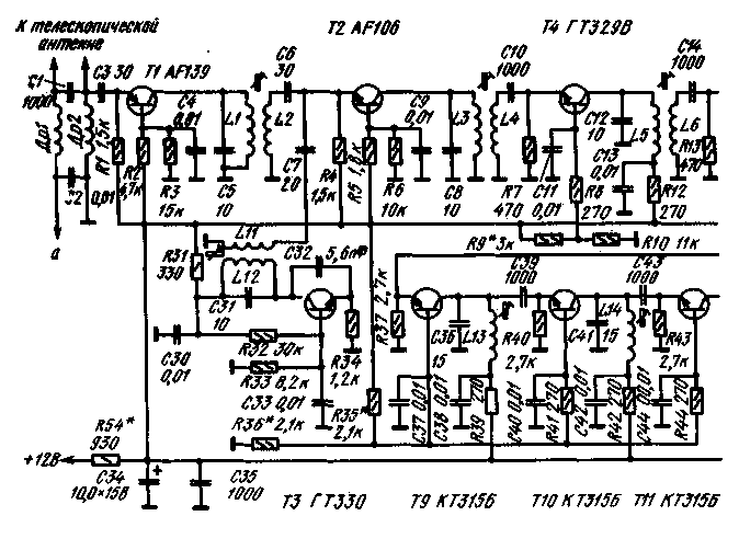
Schematic diagram of the TV (except for the blocks of the frame and line scan, a voltage Converter and voltage divider) is shown in Fig. 1.


Fig. 1. Schematic diagram of TV
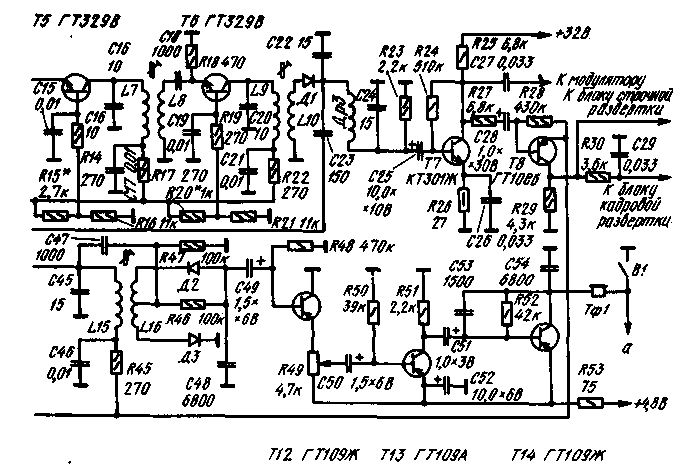
The signal from the antenna through the capacitor C1 is supplied to the base of transistor T1, which is a high-frequency amplifier. The transistor is enabled but the common-base circuit. The local oscillator is assembled on the transistor T3, the collector circuit of which includes a tuned circuit L12C31. With coil connection L11 the lo signal is fed to the mixer (transistor T2). Here comes the amplified television signal (with coil L2). The converted signal is amplified by transistors T4-T6, which are part of the intermediate frequency amplifier image (UPCI). The transistors T4-T6 is enabled but the common-base circuit. The connection between the transformer cascades.
With the release of UPCI signal is supplied to a video detector made the diode D1, and with him - in amplifier (transistor T7) and the intermediate frequency amplifier of sound (UPCS) on transistors T9-T11 connected in the circuit with a common base.
The amplified video signal is supplied to the modulator of the cathode ray tube.
The output UPCS enabled frequency detector diodes D2 and D3. Transistors T12-T14 assembled low-frequency amplifier. His load is a miniature phone TF1.
Transistor T8 is executed amplitude selector clock. The division of personnel and carry out vertical sync integrator chain R30C29. Allocated staffing and lowercase sync pulses are received respectively in the unit frame and line scan.
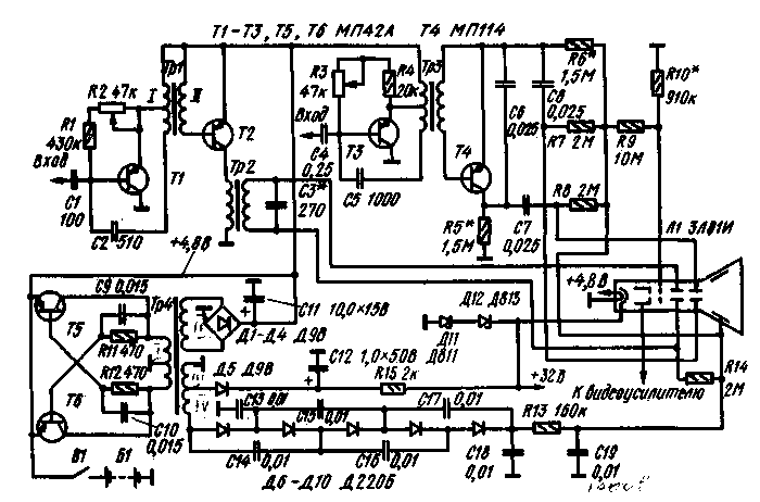
TV "cornflower" is a modernization of miniature TV, developed by participants of the XXIII all-Union radio engineer exhibition Yu Reutova. The number of nodes (blocks line and frame scanning, power supply) "Cornflower" is the same as in the TV Yuri Reutov. A schematic diagram of these nodes is shown in Fig.2.

Fig. 2. A schematic diagram of blocks lowercase and personnel scan and power supply
The setpoint generators lowercase and personnel scan, performed respectively by the transistors T1 and T3, are conventional blocking oscillators. The output stage horizontal assembled on the transistor T2. The output stage frame scanning is based on the charge and discharge capacitor C5. The charge of the capacitor comes from the high voltage source through resistors R5 and R6. Discharges the capacitor through the transistor T4. which opens with the arrival of a pulse from the master oscillator frame scanning.
For obtaining all necessary for the TV power voltages used push-pull Converter transistors T5 and T6 and the voltage doublers.
Design and details. For the convenience of TV repair made from a separate self-contained blocks. Details in blocks should be used small.
Chokes DR1 and dr2 do can be wound on ferrite rods used in the circuits of the intermediate frequency portable transistor radios. Chokes should contain about 50 turns of wire PELSHO of 0.16.
All coils are wound on textolite frame with a diameter of 5 mm. Setting the core diameter of 4 and a length of 4 mm made of brass. Coil L1 contains 11 turns of wire sew-2 of 0.41, L2 - 4 turns of the same wire, L3, L5, L7 and L9 - 20 turns of wire sew-2 0,23, L4, L6, L8 - 6, a L10 - 12 turns of wire sew-2 0,23, L11-2 turns of wire sew-2 0,35, L12-8 turns of the same wire, L13-L15 - 60 turns of wire sew-2 0,23, L16, L17 - 15 turns of the same wire.
The inductance of the inductor Dr should be about 70 mg.
Transformers TP1-TP3 formed on the yoke SCH of permalloy 50N. Winding I of the transformer TR1 includes 350+350 turns of wire PEL 0,12, winding II of 110 turns of the same wire. For winding transformers TP2 and TP3 used the wire sew 0,06. Winding I of the transformer TP2 has 350 turns, winding II - 2500 turns, winding I of the transformer TP3 - 1200+1200 turns, winding II-390 turns.
Transformer TP4 is made on the annular ferrite core MN (size core CHH). The winding of I contains 15+15 turns of wire PELSHO 0,41, winding II - 20 turns of the same wire, winding III - 100 turns, and the winding of the IV-200 turns of wire PELSHO of 0.12.
The establishment of your TV is performed by the standard technique and the article is not given.
Literature
1. Best design 27 exhibition of creativity of radio fans. M. DOSAAF. 1977.
Author: A. Gusev; Publication: N. Bolshakov, rf.atnn.ru


