


")

This TV is designed for individual viewing of telecasts on the first, second or third channels within a radius of three to five kilometers from the telecentre. It used a cathode ray oscilloscope tube. The image size is 30 mm in diameter, the clarity of the image 100-150 lines, the color of the screen is green.
Despite such a small image size and low clarity, the TV allows you to watch the main show the progress of the action. The sound is listening on a tiny phone TM-2A, and the wire connecting the phone with the TV, is used simultaneously as receiving antenna. The size of the TV HH mm weight with power supply - 500 g. the TV is powered by three connected in series silver-zinc batteries SP-1,5 placed in its case. These batteries ensure the normal operation of the TV for about 1-1,5 hour. The power consumed by the TV is about 4 watts (almost 3 watts is consumed in the intensity of the cathode ray tube). The TV is assembled on 15-transistors, semiconductor diodes 14 and the cathode ray tube SLI.
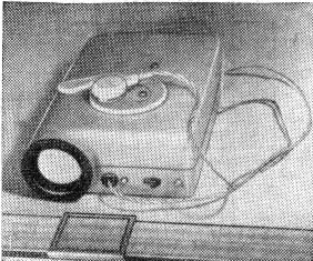
Mounting the TV performed on three printed circuit boards. To reduce the size, but also because of the small margin around the image brightness and the sensitivity of the TV does not contain any controls except the power switch and handles adjust line frequency and frames, which are derived under the slot. TV appearances presented in Fig. 1.
A schematic diagram is shown in Fig.2
The receiving portion is collected under the scheme forward gain (the use of superheterodyne scheme would require the introduction of additional control - knob lo), and the main amplification is performed after detection.
The RF amplifier is a two-stage transistors TT included in the scheme with a common base. It is designed mostly to provide . the selectivity of the TV. After detecting the video signal is amplified by a three-stage amplifier transistors T6-T8. All three of the cascade amplifier are connected electrically and by a deep negative feedback DC (resistors R13, R15), which stabilizes the modes of the transistors.
The amplifier provides a bandwidth of 50 Hz - 1 MHz with a noise level of 32 dB maximum output voltage of 20 V. It is easy to build, stable and takes up little space. To expand the bandwidth of the video amplifier of more than 1 MHz in this case does not make sense, because, firstly, due to the imperfect focusing of the cathode ray tube SLI and its quite a long afterglow still fail to realize higher definition image, and, secondly, it would lead to unacceptably high power consumption on the power to the TV. The amplifier consumes a current of 3.5 mA at a voltage of 24 V.
Frequency-modulated carrier frequency sound enters the detuned circuit L3C7, where frequency modulation is converted to amplitude, which is detected by the amplitude detector diode D2. Proyektirovanii the sound signal is amplified in a three stage amplifier bass transistors T3-T5, assembled according to the scheme similar to the amplifier. With its output voltage sound served on a tiny phone.
Since the wires connecting the phone with the TV, simultaneously used as an antenna, they unleashed LF.and HF by means of chokes DR1 and dr2 do, and capacitors C1, C2 and C10.
Amplitude selector clock is assembled on the transistor T9, personnel synchronizing pulses are separated from lowercase simplest integrating chain R23С15.
Specifies the horizontal sweep generators on the transistor T10 and the vertical deflection transistor T12 collected on similar schemes and are conventional blocking oscillators. The output stage line scan has no peculiar features. In the output stage of the vertical scan of the capacitor C21 is charged during the forward stroke through resistors R28 and R29 DC voltage 550. in and discharged during the return stroke through the transistor T13, which is periodically opened by the pulses of the master oscillator. Thus on. stress on the capacitor C21 and the transistor T13 has a span of about 100 V.
To get all DC voltages required to power the TV, including high voltage for the cathode ray tube, serves as a push-pull Converter, assembled transistors TT by multiplying the voltage. Constant voltage at the cathode and the modulator tube are chosen so as to provide acceptable contrast and brightness of the image.
Key components of the TV are mounted on two PCBs dimensions H mm. placed On the same Board voltage Converter, the RF amplifier and bass amplifier sound module, on the other amplifier and generators scans. These boards are screwed to a metal cassette, which houses the batteries. In the space between the scans and blocks voltage Converter circuit Board placed the selector clock dimensions H mm.
The Cabinet is composed of two halves, pressed hot sheet of vinyl plastic with a thickness of 1.5 mm.
When assembling the TV used parts if possible smaller sizes. Capacitors C8, C9, C11 - C13 type AMY, C14, C25, C26-C50-3, s-s - MBM 160 In, C34, C35 - BMT-1 at 400 V. the Resistors R24 and R26 - SPO-0,15. The transistor T13 specially selected - it needs to withstand a reverse voltage of at least 100 V. here to Apply germanium transistor Paragraph 26 is not recommended, as it quickly breaks down. The other transistors do not require any selection. In the amplifier In H can be applied (except indicated in the diagram) P403 transistors, P, P, scan generators (except T3) and the Converter MP39-MP41.
Chokes DR1 and dr2 do the TV wound on ferrite rods used in the inverter circuits radio "Neiva" ("Jupiter", "Signal") and contains 50 turns of wire PELSHO of 0.16. These coils L1, L2, L3 are summarized in table. 1, and transformers - in table. 2.
Table 1
NN TV channels
Coil L1
Coil L2
Coil L3,
the number of turns
wire
the number of turns
wire
the number of turns
wire
1
12
PELSHO 0,41
13
PELSHO 0,31
11
PELSHO 0.41
2
9
"
12
PELSHO 0,41
9
"
3
6
"
8
"
6
"
Coils are wound in a single layer round plastic frames with a diameter of 3 mm and a length of 9 mm. They are placed in a rectangular screens sizes 9x9x14 mm and configured cores made of ferrite NN diameter of 2.3 mm and a length of 9 mm.
Table 2
NN transformers
under the scheme Core N windings The wire: mark
and diameter, mm The number of turns TP1 The permalloy 50N SH I
II 350+350
110 PEL 0,12 TP2 Too I
II 350
2500 Sew 0,06 TP3 The same I
II 1200+1200
390 " Tp4 The ferrite ring
NN CHH I
II
III
IV 15+15
20
100
200 PELSHO 0,41
"
PELSHO 0,12
"
Author: Yury Reutov; Publication: N. Bolshakov, rf.atnn.ru