The Converter allows you to use TV sets of old samples, as well as TVs, 3rd and 4th generation, not having ACS unit for receiving UHF.
Converter allows you to view TV broadcasts in the UHF range from 21 to 60 channels with conversion to meter range with 1 to 12 channels. Connects the Converter to the antenna input MB TV.
Schematic diagram of the Converter shown in Fig. 1. It consists of a radio frequency amplifier, mixer, local oscillator (lo).
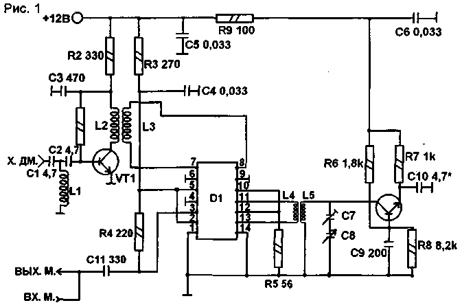
The radio frequency amplifier is assembled on a microwave transistor VT1 type CTB, the Converter is assembled on a chip CPS that is especially designed for use as a mixer.
As a local oscillator transistor is used CTA included in the scheme with a common base.
The UHF signal coming from the antenna, the dedicated circuit C1, L1, C2, is amplified by the transistor VT1, and loop L2, L3 is supplied to the chip D1, which is converted into a frequency meter range.
The local oscillator operates at frequencies from 421 MHz to 560 MHz. T. e. override 139 MHz, which allows you to convert any of the UHF channels from 477 789 MHz to MHz in the meter.
So, for example, to convert the 21-th channel in meter, it is sufficient to configure the local oscillator to the frequency 421 MHz received 477 MHz - 421 MHz = 56 MHz, i.e. 1-th channel, and similarly on other channels, while other channels can get up to 5 channels metre range (see tab.1).
Table 1
N UHF channels
N meter channels
N UHF channels
N meter channels
N UHF channels
N meter channels
N UHF channels
N meter channels
21
1
31
1,2,3,4,5
41
4, 5, 6, 7, 8, 9, 10
51
6,7,8,9,10, 11. 12
5,6,7,8,9,
6, 7,8, 9,10,
22
1
32
1,2,3,4,5
42
10, 11
52
11,12
23
1,2
33
1,2,3.4,5
43
6, 7, 8, 9, 10,11,12
53
6,7,8,9, 10, 11,12
24
1,2
34
1,2,3,4,5
44
6, 7, 8, 9. 10,11, 12
54
7,8,9, 10. 11, 12
25
1,2,3,
35
1,2,3,4,5
45
6, 7, 8, 9, 10,11,12
55
8,9, 10. 11, 12
26
1,2,3,4
36
1.2,3,4.5
46
6,7,8,9, 10.11,12
56
9,10,11,12
27
1,2,3,4,5
37
1,2,3,4,5
47
6, 7, 8, 9, 10,11,12
57
10,11,12
28
1,2,3,4,5
38
2.3,4,5,6, 7
48
6, 7, 8, 9, 10,11,12
58
11. 12
3, 4, 5, 6, 7,
6, 7, 8, 9,
39
• 8
49
10,11, 12
59
11, 12
40
3,4,5,6,7, 8,9
50
6, 7, 8, 9, 10,11,12
60
12
The Converter is powered stabilized power supply 9...12 V supply current not exceeding 30 mA.
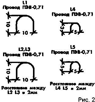
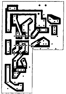
Constructive data of the coils shown in Fig.2, the circuit Board drawing in scale 1:1 - in Fig.3.
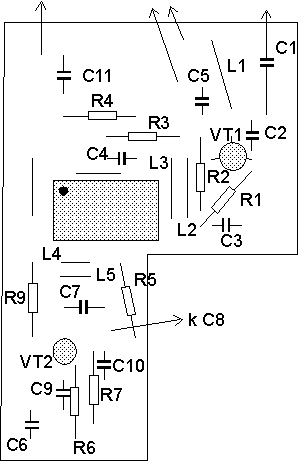
In the Converter resistors are used for C1-4-0,125; capacitors C1, C2, NW, C9, C10 - type KD-2, capacitors C4, C5, C6 - type K10-7B, the capacitor C7 - type CT-23 8/30 pF, capacitor C8 from УSW of the receiver unit "Ocean".
Details of the Converter are placed on single-sided PCB from foil fiberglass with a thickness of 1 mm. the Converter is placed in the body of a standard unit of access control. Cascade lo is separated from the rest of the Converter by a partition made of tin.
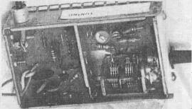
Fig.4.Adjustment of the Converter is reduced to the building of the local oscillator at the desired frequency.
At maximum capacitance of the capacitor C8 with slow rotation of the capacitor C7 are seeking admission of the 21st channel on the 1st channel, and when the minimum capacitance of the capacitor C8 with slow rotation of the capacitor C7 are seeking admission to the 60-th channel to 12 channel.
In this configuration, all channels of the UHF band fall into the lane conversion Converter.
Literature
Authors: V. Korobeynikov, G. Borisov; Publication: N. Bolshakov, rf.atnn.ru


