


")

Circuit breakers by the end of television programs and timers at the specified time in modern TVs is not always convenient. Older TVs they do not. Therefore, some hobbyists use they have developed a stand-alone unit extracts time working in dialog mode. Published a description of another one of the options such timers-machines.
Many modern TV sets equipped with special devices, automatically disconnecting them from the network at the end of the program guide (the loss signal) on the selected channel. In addition, in such devices use also programmable with remote control timers that turn off the TVs using in advance selected intervals. However, they are not always satisfied with the viewers. For example, you urgently need to leave home in a hurry and you didn't turn off the TV and the timer is not set for a certain time interval. Another example - during the transfer, you fell asleep without turning on the timer and the TV is on round-the-clock channel. In the first case it will work to your parish, and in the second - until you Wake up, which, of course, unsafe.
The proposed repetition of the timer-the machine based on the principle of "dialogue" with user the same way as is done in [1]. The machine is a stand-alone unit, which serves voltage. The device come next a place where the viewer is watching the broadcast. Since the distance to the screen can reach several meters, then the TV connected to the machine network extension of the required length. Interference in the units is not required. It is important only after connecting with a timer switch network TV in the "on" position. Turn on or off the device will be ensure the timer.
After a certain period of time selected from the range optimally, according to author suitable intervals to view these or other programs, device beeps, as if asking the user whether to keep the TV is on. At the same time this signal warns that the device soon will be disconnected from the network. If you wish to continue viewing the programme the viewer need for a sound signal, briefly press the "repeat" and the machine will start again to count down the preset shutter speed. If it is not already happy owner of a TV, it should change the switch to "Interval" and then click on "retry". In the absence of this command, the timer disconnect the machine from the network and switches itself off.
The machine provides switching load power up to 1 kW. The current consumed the timer from the power supply in a mode the shutter speed is 70 mA, and the feed mode beeps - 90 mA. The device is designed for time intervals of 15, 30. 45, 60. 90 and 120 min. Timer can be used not only with TV but with other electrical appliances.
Schematic diagram of the timer shown in Fig. 1. Due to its simplicity in mainly the use of chip CRES, which is a device with a variable division ratio of the frequency and is intended for use in as the delay component in the time relay [2 - 5].
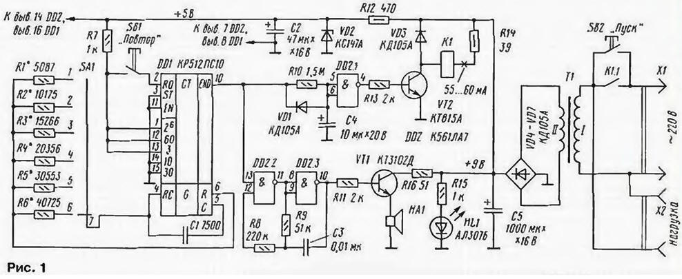
(click to enlarge)
Exposure time set by the switch SA1. Interval - switching resistors R1 - R6. If you need high precision, you need to pick up quite carefully. In our case it is not required, so it is sufficient precision 1%, i.e. two or three characters. In the diagram, the resistors shown are single, and actually each of them may consist of several resistors connected consistently. In position 1 of switch SA1 exact frequency (in the diagram the resistors R1 - R6 are indicated for such a case) internal generator chips is $ 13106 Hz. and exposure time - 15 min; in position 2 - 6552: 3 - 4367. 4 - 3275. 5 - 2182.6 - 1637 Hz with a corresponding change exposure time: 30. 45. 60. 90 and 120 min In the selection of resistors R1 - R6, the author used electronic multimeter. But you can control the frequency at the output of the R (pin 6 of the chip DD1) electronic frequency meter. Code 11100, present on the inputs of the installation of the frequency divider corresponds to the division ratio of 23 592 960.
Before you start, device select switch SA1 temporary need interval. Further short-term (1…2) press the button SB2 "start" and include the device. In this case, the voltage supplied to the load, the output rectifier VD4 - VD7 appears a voltage of +9 V and HL1 led is lit. signal the timer and start timing. With parametric stabilizer consisting of elements R12. VD2. C2. voltage +5 V comes to the DDI chip. Its inside the generator starts to produce pulses with a frequency determined by the elements castorocauda circuit: condenser C1 and one of the resistors R1 - R6.
After the supply voltage is connected at the output END of the chip level appears DD1 0. He goes through the diode VD1 to the inputs 5 and 6 of the inverter DD2.1, the output which raises the level 1, which through a resistor R13 opens the transistor VT2. The current flows through the relay coil K1, it works, your continue the contacts K1.1 button SB2 "start". In this case, after releasing the button, the device will remain enabled.
The level Of output END of the chip DD1 is supplied also to the input (pin 13 of the element DD2.2) generator control sound signal collected on the elements DD2.2. DD2.3. R8. R9, C3, which is switched off.
Level 0 at the output END of the chip DA1 will continue until then. until you run out set the time delay, after which it will change to level 1. Last start up the generator of the audio signal. With its output pulses with a frequency of 1 kHz using transistor VT1 is coming to the emitter of the sound HA1.
In addition, the level 1 closes the diode VD1. The capacitor C4 begins to charge through the resistor R10. Transistor VT2 will be open for about 10c (τ = 0,7·R10·C4).
During these 10 s you can change the time delay switch SA1 "Interval" and (or) to restart the timer button SB1 "snooze". If neither one. nor the other is not is done, the capacitor C4 is charged up to level 1. inverter DD2.1 switches, level 0 at its output closes the transistor VT2. relay K1 de-energized, the contacts to 1.1 opens, disconnecting the load and himself from Ajmer network.
Button SB1 "repeat" resets the output END of the counter circuits DD1 and can be pressed at any time during the exposure time. Consequently, this extract can to change at any time, it is only necessary after each change of position switch SA1 press SB1 "repeat" so that the exposure time match the set value.
The timer is assembled on the PCB of one-sided glass fiberglass. The variant of the trace conductors depicted in Fig. 2 with location details.
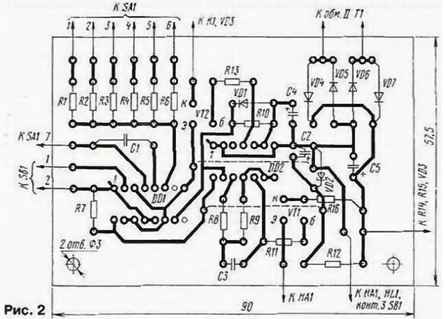
The transformer T1 should ensure the voltage on the capacitor C5 is +9.. 12 V.
Chip CLA (DD2) interchangeable on CLA,LA. The emitter HA1 - phone the capsule or dynamic head 0.25 GDS-20-50 (or other impedance of 50 Ohms).
The resistors R1-R6 - C2-29B, and the rest of the IFL. Capacitors (C) and C3 - km-5, km-6 (WITH 1 TKE no worse M750J. C2, C4. C5-C50-16. K50-35.
Diodes KDA (VD1, VD3) interchangeable on KDB. Bridge VD4-VD7 collect diodes CD with any letter index. Instead of the transistor KTA (VT2) will fit any in this series. Transistor KT3102 (VT1) also, any of this series or CTA - CTE.
The device may be operated relay trip current 55…60 mA at a voltage of 7.5.-9 In (the author used powerful role RPM-215-TIES, passport unknown). The relay contacts and buttons
SB2 should be designed for switching AC voltage of 220 V and the rated load current.
Establishing device is reduced to the selection of resistors R1 - R6. as it was above.
Literature
Author: E. Zuev