


")

Modern man from all sides daily advertising and surrounds better than adjusted flow pouring on us from all sides of the information, the sooner we can treat it as a necessary source of information - the guide to action when making purchases or receiving certain services. Many entrepreneurs have already felt a tangible effect from information that regularly appears in the media, advertising their products and services. Additional effect can have a "local" advertising meeting the passenger at the threshold of Your office or store. It can be brief (1…16 seconds) of audio or video information that starts automatically when opening the door (or Elevator doors), and not repeated often specified length of time, avoid its annoying. (The economy must be economical, and the ads are not Intrusive). Digital dispenser advertising (hereinafter CBD) - the launch of the advertisement and regulation of the length of the pause after it, during which the re-launch of advertising is not possible.
CBD (see Fig. 1) includes the command source of advertising information - digital tape recorder, and prohibits restarting of the advertising message at a time determined by timer No. 2. Sensor for start-CBD, button SB1 is "start". The main burden of CBD - a digital tape recorder that is activated by a negative slope at the entrance "PLAYE" (pin 24) DA1. Additional load CBD - various musical devices or the more powerful USC (driven, for example, power, or input "MUTE") - can be switched on for a time equal to the duration of the advertising message (set by timer No. 1) - normally open contacts of relay K1 (Fig. 1, not shown) included in the supply circuit break of these devices.
Fig. 1. Schematic diagram of the device
For writing advertising messages digital recorder press and hold the button SB2 "Record". Recording is possible until the led lights HL1 (for chip type ISD1416 for 16 seconds). Then digital tape recorder is automatically set to the starting position and ready to play, or (if necessary) to a new record. To record on a digital recorder can at least 100,000 times, and the recording is saved to a hundred years, even in the complete loss of power.Works CBD as follows. On closure of switch SA1 "Power" through resistor R2 to charge the capacitor C1. Thus during the entire rise time of the voltage fed from the output of the adapter, side " - " of the capacitor C1 is formed by the non-inverted pulse of positive polarity, providing installation triggers DD2.1 and DD2.2 in the initial (zero) state. The front door is opened causes the opening of contacts 1 and 3 buttons SB1 and high logic level through the resistor R1 (the enforcer chattering from contacts button is not needed) is supplied to pin 2 logic element DD1.1. Since logic element DD1.1 pin 13 is connected to a common wire, DD1.1 performs the function of logical multiplication (2I). At its output 1 inverting output (pin 2) trigger DD2.1 is given a logical unit permitting passage of the high logic level output 2 DD1.1 at the inputs (pins 3 and 11) triggers DD2.1 and DD2.2, respectively. Triggers fire and non-inverting outputs (pins 1 and 13 respectively) appear unit. The indicator HL1 begins to glow yellow-red, the VT1 transistor opens and the relay K1 is actuated, closing the supply circuit of the additional load. Simultaneously, negative differential inverting output (pin 12) DD2.2, fed to the input "PLAYE" (pin 24) DA1, includes DA1 digital tape recorder on playback.
Single vibrators ("timer # 1 and timer No. 2") are collected at the counting triggers DD2.2 and DD2.1 respectively according to the same schemes and differ only in their time-setting circuits. So let's consider how the timer works only No. 1. The appearance of a positive differential at the input (pin 11) of the element DD2.2 overwrites the information (logical 1) from the input D to the non-inverting output (pin 13) of the trigger. In this case, the diode VD2 is closed, and slowly capacitor C3 begins to charge through resistors R6 and R7. When C3 is charged to half the voltage of the power supply, the output pin 8 logic element DD1.3, performing the function of "2OR", a logical 1 appears. This logic 1 is fed to the input "Reset" (Reset) to pin 10 of flip-flop DD2.2 returns "cocked" the trigger to its original state. That is on pin 13 DD2.2 is set to logic 0. Capacitor C3 is quickly discharged through the diode VD2, the indicator HL1 changes the light color to green, the relay K1 releases, and a digital recorder so ends the play and is set in the initial state. When this timer No. 2 assembled on the trigger DD2.1 continues to operate. The logic zero level at pin 2 of flip-flop DD2.1 continues to hold in the closed state of the element DD1.1. The element DD1.1 performs the function of "2," and a logical zero at its output 1 prohibits the re-start button SB1 exhaust timer No. 1 before the expiration of timer No. 2.
Upon completion of timer No. 2 indicator HL1, previously lit in green, goes out, indicating that the ban re-launch of the advertising message has expired and digital tape recorder is switched on again, if you click on the SB1.As a digital tape recorder used chip ISD1416 - single-program recording reproducing device with the ROM, preserving in time the recorded information even when the power supply voltage. ROM size depends on the applied type of chip DA1 - last two digits in the designation indicate the appropriate volume (in seconds). Figure 1 shows a chip DA1 digital recorder has the ROM to record for 16 seconds; maximum current in the sampling mode of the crystal (during recording and playback) not more than 15 mA; current consumption in standby mode - 0.5 mA.
Using the CBD as follows: 1). Turn on the power toggle switch SA1. 2). For the recording of the advertising message, the microphone shall be located at a distance of 5 to 50 centimeters from the source of sound is pressed (and held down the all time record) button SB2 "Record". 3). Within the required time (1 … 16 seconds) is recorded. The extinction of the LEDs HL2 (hold down the button SB2) suggests that the recording time has expired. 4). Then the power can be turned off to ensure that the recorded fully retained when the power is off. 5). To play a recorded advertising message, turn the power on, short press the SB1 "start" and listen to an advertising message on the built-in dynamic head BA1. After playback, briefly led flashes HL2. 6) Time (30 … 150 seconds), during which there is no re-run of the advertising message, is set by an advertiser potentiometer R3.Setting the CBD is as follows: a Trimming resistor R6 sets the duration of a pulse of positive polarity at the output of the single vibrator (pin 13) DD2.2 is equal to 16 seconds. This is required only for synchronous (digital tape recorder) additional devices that are switched by means of a relay K1. Digital tape recorder turns on and plays to the end recorded with negative slope (and not in the presence of low level) input "PLAYE"(pin 24 DA1). To work with the external USC trimming resistor R10 sets the required for the "swing" of USC the output level of the digital recorder. Control speaker BA1 if needed off toggle switch SA2. The maximum time of the ban re-enable the advertising message can be increased by increasing the value of capacitor C2. After that, the desired minimum time of the ban re-enabled (30 seconds) can be specified resistor R4*, the resistance of which it is permissible to reduce to 10 the shortfall. Scale R3 graduated by increments of 30 seconds.
In the CBD used fixed resistors type OMLT of 0.125, variable resistor R3 type CP3-23a (slide); R6, R10 - trimmers CP3-38b, capacitors C1, C4, C9, C10 type K50-35; C2, C3 - C50 - 29 or similar foreign production; C5 - C8, C11 CM or any ceramic buttons SB1, SB2 KM1-I. Diodes VD2 VD1 … you can use any silicon, for example CD, CD - KD522. Relay K1 RES - (RS4.529.031-04) with the weakening of the springs, or the other, triggered at a voltage of 3.5 Volts and allowing the switching of the mains voltage. Transistor VT1 is possible to replace such composite transistor CTB(A). Chip DD1, DD2 - series 564 or C.Digital tape recorder DA1 can be type ISD1416, or similar (with the time of the recording-playback 20 seconds - ISD1420). Dual color led indicator HL1 permissible to replace two single, for example ALE (yellow) and FYL-5013UBC. (blue glow). BA1 - of any type with an impedance of 16 … 50 Ohms, for example 0,25 GDS-2; 0,25 GDS-3-8; GDS-1. The microphone WM - electret, for example NMC. In the absence of chip CLP (three logical element "majoritarily") logic elements (2I, 2OR), created on its basis, is replaced by equivalent circuits for the diodes and resistors in accordance with figure 2.
Fig. 2. The equivalent circuit in the absence of chips
As a constant current source for the CBD, you can apply the power supply, shown in figure 3. Will also fit any portable "adapter", such as built-in power plug, providing a stabilized output voltage of + 5 Volts and a current of at least 100 - 200 mA. In the author's version used a homemade power supply, consisting of widespread transformer TCE-110, used in tube TVs diode bridge CCA, oxide filter capacitor 1000 UF ? 16B and voltage regulator [1].In the secondary winding of TCE-110, having an output voltage of ~ 14 Volts and rated current up to 1 ampere made a disqualification for receiving voltage ~ 7,5 … ~10 Volts. To disassemble the transformer for this purpose is not required. 14-volt winding is wound on top of the other, so quite a bit to cut the protective paper wrapper and tweezers "to visiplot" laterally outermost turn of the second or third (counting from the top) layer of the winding. To a selected coil of the two or three "visiotech") carefully so as not to make inter-turn short circuits, soldered the pipe from the mounting wire bundle. (Lacquer insulation of the winding wire is removed with a scalpel at the length of 5…10 mm, the wire is wetted by liquid rosin, oblizyvaetsya and only then soldering is performed).
Fig. 3. A constant current source
Wanting to use USC and, thus, to use one common power supply +5 Volts, the author to work with the CBD applied previously made USC depicted in figure 4. The main parameters of USC when working in the range of operating voltage +5 … +15 Volts is shown in table 1. In principle, this action USC can operate at a voltage of + 25V, giving in chetyrehosnuju load power 40 Watt.
Fig. 4. USC
Table 1
The voltage +5V +6V +8V +9V +12V +13.5 V +15V Settings And BX.(sweep) 0,028 In 0.04 b 0,057 In 0.076 mm In 0,106 In 0.12 b 0.14 In Ivih.(sweep) 1,8 2,8 3,8 5 7,6 8,4 9,4 I ponv., And 0,16 0,18 0,32 0,45 0,67 0,78 0,87 I rest, And 0,025 0,028 0,04 0,045 0,06 0,08 0,11Most of the elements of the CBD is installed on a PCB (printed circuit Board) (figures 5, 6, 7) of two-sided foil fiberglass (Micarta) size 53,5 x 61 x 2 mm. with the Exception of relay K1, which is set in sockets intended for connecting additional (~ 220 V) switched load. (Long wire switched network ~ 220 V, passing near the elements of PP, can give clues to the microphone amplifier circuit CBD). In addition, the installation of K1 out of PP allows you to "disengage" from the drawing of PP and used as the K1 relay other types.
Fig. 5. The printed circuit Board device
Fig. 6. The printed circuit Board device
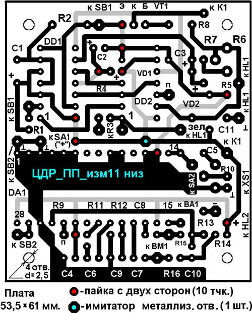
Fig. 7. The printed circuit Board device (bottom)
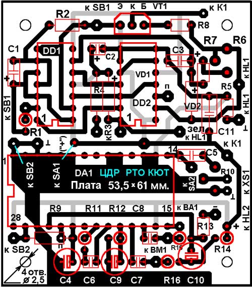
Fig. 8. The printed circuit Board device
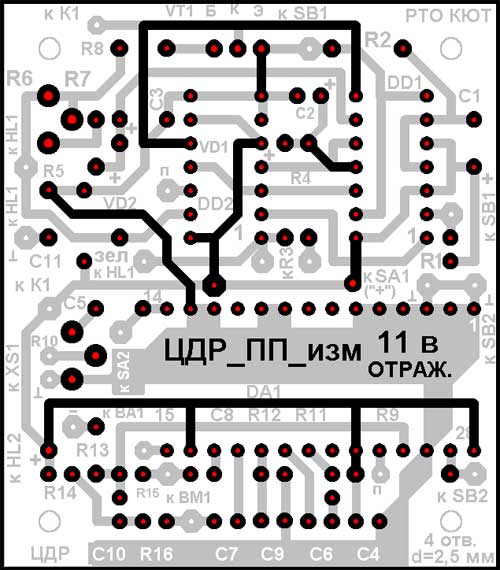
Fig. 9. The printed circuit Board device (reflection)
If it is not possible to produce PP with plated holes, for ease of soldering radio components are mounted on PCB with a gap of about 5 mm. At PP 1 set wire retainer in isolation, 1 x simulator plated holes, and in ten points the conclusions of electronic components propaedeuse on both sides, PP. Structurally, the PP is attached (through a layer of insulation) by four screws M2,5 to the housing wall, covered with sheet copper foil size 53,5 x 61 mm. Foil serves as a shield and is electrically connected to the common wire CBD. In the absence of a thin foil can be applied sheet materials (copper, brass…) and a layer of insulation, which excludes short-circuit between the screen and the PCB. The mounting screws on the PP are shared for fixing the screen and a layer of insulation. In the presence of a "stack bolts"([hollow cylinder with thread, priklepyvanija (or resultshowever) to the wall of the housing, a screen and a layer of insulation is recommended to prilepite to the wall of the housing. Elements SA1, SA2, SB2, R3, BA1 mounted on the front wall of the housing. The findings of the LEDs HL1 and HL2 are extended to a size approximately equal to the thickness of the CBD or are mounted on the front wall of the housing and to fluster PP flexible circuit conductors. The taps of the sensor button SB1 is made twisted pair or shielded wire to prevent false inclusions of CBD.If there is no need to switch additional load elements R1, R7, VT1 can be eliminated. Normally closed contact of switch SA1 "Power" it is recommended to connect to GND through a resistor R EXT. type OMLT 0.25 resistance 10 … 22 ohms for rapid discharge of capacitor C4. This is necessary in case if the power supply to the CBD in the play mode turns off the switch SA1, and then again immediately should be included. Without additional R not fully discharged capacitor C4 for a few seconds does not allow digital recorder DA1 (with snapshot turned on again) be installed in its original position ("stop and rewind the tape").
Notes:
- implemented by an instance of the chip ISD1416 had indicated in Fig. 1 the values of 18 (not 16) seconds of the recording - playback.
- Files drawings PP, marked with the letter t - for boards with thermal transfer of the pattern trace.
Author: Oznobishin A. I., This email address is being protected from spambots. You must have JavaScript enabled to view it. ; Publication: www.cxem.net