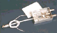
 If you have the equipment for reception of programs "NTV+", her you can extend and adopt programs that are relayed to other satellites for example, from the group "BIRD NOTES" (13° e). This task is dedicated the present article.
To receive satellite TV programs in our country use the antenna diameter of 0.9 m or more. However, few know that much of the European the territory of Russia it is possible to take not only "NTV+", but the program with satellite "HOT BIRD". For this you need to additionally install the Converter the range of 10.7 11.7 GHz...(or more broadband to 10.7 12.7 GHz...). For convenience in this case, the necessary two-input receiver. Unfortunately, in most cases, the sets of programs "NTV+" enter receivers NTV-2000" or "NTV-1000", who only have one microwave input. Do the same any mechanical switches for switching two converters unlikely convenient. It is desirable that this is done automatically when switching channel. Description of such a switch is shown below.
The circuit of the switch, which is installed at the input of the receiver in the form of consoles, allows you to automatically switch the two converters are shown in figs. 1. The device comprises an adder, assembled on a hybrid coupler (T1 R1). To his inputs via capacitors C1 and C2 connected to the outputs of the first and second converters, respectively. The adder provides isolation between outputs converters and thereby reduces the effect of connecting cables converters each other. Output device is connected to the input of the receiver, and from the latter supplied voltage converters. However, the power is supplied only on one of them, and therefore will work only one. And here is what it depends on in what position are the contacts K1.1 electromagnetic relay K1.
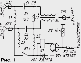
When the relay is de-energized (shown in the diagram), the voltage from the receiver through the transformer T1, inductor L2, L3 and the contacts of the relay comes on the Converter is connected to "Input 2". If on the bus "Management" submit permanent voltage more than 1.5 V, the transistor VT1 is opened and relay that receives the voltage from the receiver, it will work. Your contacts it will shut off the power with Converter connected to "Input 2", and submit it to the Converter connected to "Input 1".
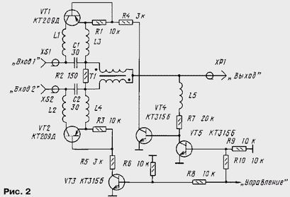
In the device assembled according to this scheme, the relay is supplied with the voltage coming in the converters. Therefore, the relay must be economical, as it additionally load the power source Converter. If the relay is unable to purchase or the current consumed by the actual device, it is necessary to reduce to a minimum, as keys you should use transistors, and to collect the relay according to the diagram shown in Fig. 2. Here, the power supply to the Converter is also through the transformer T1, one of the transistors VT1 or VT2 and relevant inductors L1 - L4. These transistors is falling a part (0,3...0,4 In) of the supply voltage. When on the control bus will be a voltage exceeding 1.5 V, transistors VT3, VT5 will open, this will open and the transistor VT2, and supply the voltage fed to the Converter is connected to "Input 2". When administering the bus is the voltage less than 1 V, the transistor closes and opens VT4, VT1, and the supply voltage will flow to the Converter is connected to "Input 1". The actual device will consume a current not exceeding 6...7 mA.
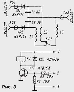
The adder on the hybrid coupler provides very high isolation between cables converters reduce the microwave. Better isolation can be achieved by applying special microwave switching diodes, for example CAA. The switch scheme for this case is shown in Fig. 3. It is very similar to the scheme in Fig. 1, and switching voltage relay is. But in a signal bus are included switching diodes VD1, VD2, which are opened only when they is energized with the relay. And both the microwave signal and the supply voltage on the Converter is supplied via a diode. Part of the supply voltage (about 0.7 V) falls the diode, but it usually does not affect the normal operation of the Converter. Due to the fact that in the closed state, the diode has great KAA resistance and small capacitance (share pF), provides small influence of the cable reduce dNTPs Converter. In the on state the diode has small resistance losses (1...2 Ohms), so the loss of signal power small.
Structurally, most of the elements of any of the variants of the device is placed on the PCB from double-sided foil fiberglass thickness 1...1.5 mm. One side leave metallized, and the width the conductors, which is transmitted microwave signal must be equal to the thickness of the Board - this will provide a better matching of the device with the Converter.
For devices made according to the scheme in Fig. 1, a sketch of the circuit Board shown in Fig. 4. To its metallized side using the holes soldered conclusions the emitter of the transistor and the resistor R2. In addition, the area to which solder the output cable is connected to the foil on the edge of the Board with its second side.
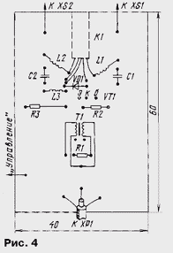
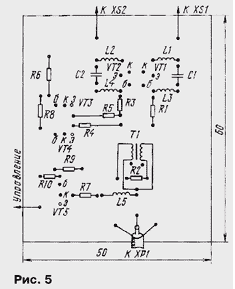
Charges are set in a metal case. On the wall of his post input socket XS1, XS2. A separate case can not do. In this case, the side walls, which should be made of tinned copper or brass strips having a width of about 20 mm (will fit and coated fibreglass), soldered to the PCB with four sides and then probailout their joints together. Previously in one of the walls make a hole for receiving a high-frequency connector, and the other holes for cable and wire for supplying a control voltage. After debugging and verification device can be closed by a removable cap or solder. For the device assembled according to the scheme in Fig. 2, a sketch of the circuit Board shown in Fig. 5.
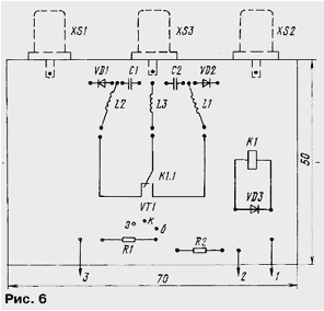
If desired, made the switch can be embedded into the body of the receiver, there is the benefit of there is enough space. A sketch of the PCB of this option and for the circuit in Fig. 3 it is shown in Fig. 6. Here nests the UHF connector, F-type soldered directly to the Board: the center conductor to the signal conductor, and the body - to her backside. Pre-housings nests should be carefully many years ago, keeping it cool to avoid damaging them.
In the device according to the scheme of Fig. 1 and Fig. 3 applicable parts: transistors CTA - CTE, CTA - CTD and similar; diode of any compact rectifier. Relay it is desirable to use small RES, RES, REC the winding resistance is not less than 0.8 ohms and a voltage of 12 V. Them got pre-check on steady alarm when the selected feed voltage. Suitable relay with a lower coil resistance and less the voltage, but then it should consistently include firefighting resistor. However, in this case the relay will additionally load the source power Converter, which is undesirable.
The resistor R1 is recommended to use high frequency - P1-12 or C2-10 by removing his conclusions and solder directly to the printed conductors. The rest resistors - MLT, S2-33 or any other. Capacitors are better to use chip - K10-17B, in an extreme case fit km-5, CD ROM, but have to shorten their findings to 1...2 mm.
Transformer T1 is made as follows. Two of wire sew-2 0,3 pass through two ferrite tube with a length of about 9 mm (chokes DM type). Then the tubes are stacked together, the ends of the wires obluzhivayut and connect in accordance with the scheme. Conclusions should be short as possible. More execution the design of such a transformer is described in "Radio", 1996, № 11, p. 12. Coil the inductance of a wound wire sew-2 0,2 mandrel with a diameter of 2.5 mm and contain 10-15 turns.
In the device according to the scheme of Fig. 2 can be applied to similar parts, only to as VT1, VT2 allowed to use transistors KT209I, CTE, CTC, KTM, CTB, CTD, CTE, CTM.
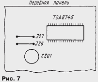
A little about the control signal. The device was switched converters automatically when switching channels the receiver can use the signals which are used to manage the individual nodes of the receiver. The most suitable for this are the switching signals of the decoding modes devices (decoders). With the remote control receiver NTV-2000" set (program) four such modes: "on" - without decoder and three modes of operation decoder - "d1", "d2", "d3". As the control signal of the selected signal, sets the mode of operation without decoder "on". This signal can be removed from jumper J28 next to the CPU (see Fig. 7). In the mode "on" on this jumper is a logic low (<0.4 V), and the rest logical 1 (approximately 4.7 In).
To supply this signal to the device at the rear of the receiver set any small socket, connecting it with the jumper J28. In the mode "on", i.e., when the decoder is disabled, the supply voltage is applied to the Converter connected to "Input 2". Therefore, the Converter for receiving signals satellite "BIRD NOTES", is connected to this input. In the mode decoder the jumper J28 be the voltage that will open the transistor VT1, will include the relay K1 and apply mains voltage to the Converter is connected to "Input 1". This entry and you should connect the Converter "NTV+". For the circuit in Fig. 2 converters need to connect Vice versa. Since the modes of operation of the decoders can be programmed with remote control separately for every channel, this is equivalent programming connect a Converter, i.e., their switching will be made automatically, in accordance with the channel number.
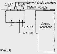
To install the switch, assembled on the circuit Board shown in Fig. 6, it is necessary to remove the rear wall of the receiver, which remove two screws and mounting nut the input of the UHF socket. In the panel, drill the holes for the jacks and put them on it nuts. Then the panel with the Board establish into place - thus the fee will stay on the nest. Conductors connect it with the receiver Board, and the power for the relay to take power bus +12 (closest to the rear wall conclusion chip voltage regulator U302). The nest "Exit" connect a jumper from the input of the receiver (Fig. 8). So he turns into two-input gates.
If the receiver you plan to use without a decoder when switching modes operation of the decoder picture and sound at the RF output and scarce "TV" in some cases may disappear. To avoid this, scarce "DECODER" connect jumper pins 1 and 2, 5 and 6, 19 and 20.
In addition, to control the switch, i.e. switching converters use signal "DEV" (two-stage change of image brightness), but then simultaneously with the switching of the converters will automatically switch and the brightness. If this is satisfied, a signal to switch off the jumper J36, which is located near the tuner (UHF unit) receiver.
Author: I. Nechaev, Kursk


