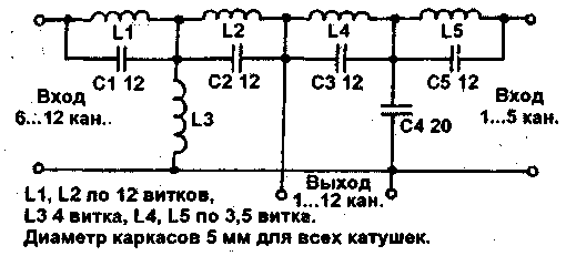
Often in practice there is a problem of unification of the two antennas of different channels on one feeder. This can apply the generic scheme shown in Fig.1.

Fig.1
Coil L1...L5 can be wound enameled wire diameter 0,5...0,6 mm on one frame, turn to turn. Note that the distance between the ends of adjacent coils should not be less than 8 mm. Can be applied frameless winding.
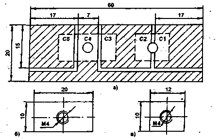
If you have no capacitors 12 and 20 pF, you can do foiled Micarta or phenolic resin. Fig.2A are cut pads. The slits have a width of 1 mm (the thickness of the cutter). Fig.26,cut out of a plate made of aluminum, duralumin or brass with a thickness of 1.5...2.0 mm.

Fig.2
These plates are applied with the foil side on the foil material, placing the pre-strip of polyethylene of a thickness of 0.1 mm. Suitable from conventional polyethylene plastic bag. In Fig.2A, the dotted lines show the location of plates on the foil. Plate according to Fig.26 forms a capacitor C3, C4, C5, plate (Fig.2B) - the capacitors C1 and C2. All that remains is to solder the coil L1...L5 in accordance with the scheme. Under the M4 screws for this purpose, you need to add spacers tinplate, which is convenient to solder the coil. For protection against atmospheric moisture is necessary to cover the entire structure with a varnish or placed in a sealed housing. The holes for the M4 screws from the side of the foil should be slightly razzenkovat, to avoid circuit capacitors via the screws on the plates.
If ham will need to make in the same way capacitors for other purposes, then you need to follow the formula:
C=(8,85*10-3*ES)/(d
where C is the capacitance in pF;
S - the area of the plates of the capacitor in mm2;
d is the thickness of the dielectric layer, in mm.
E - the dielectric constant of the dielectric.

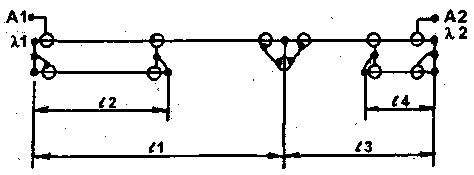
Fig.3
There is another way to foster connections TV antennas on one feeder (Fig.3). A1 - the point of connection of the active vibrator antenna, tuned to the wave of X1. The vibrator of the second antenna, tuned to the wave L2 is connected to the point A2. l2, l4 - quarter-wave balun sections of cable, the length of which is determined by the formula:
l=K(L/4),
where l is the length of the balun segment;
L is the wavelength;
To the velocity factor of the cable.
For cables with polyethylene insulation K=0,67.
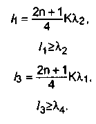
Both antennas are connected to a common feeder at the distance of the vibrators, which are determined from the system of equations:

where n is any integer.
Here form the basis of the following principles:
- quarter-wavelength line segment is loaded on the wave resistance is less, transforms it into the more resistance the wave;
- if connected to the line resistance is much more wave, it almost does not load the line.
Author: A. Zherdev, Gomel; Publication: N. Bolshakov, rf.atnn.ru


