


")

For receiving sound produced at the moment the TV is built on the so-called single-channel scheme. They fluctuations of the intermediate carrier frequency image (38 MHz) are used as heterodyne to the selection signal of the second intermediate frequency sound (6.5 MHz). With such a construction tract frequency response of the if amplifier image (UPCI) is usually optimal for signal image, not sound. Because of this, sound quality is sometimes low. In addition, when a signal of the image impossible reception and sound.
However, there is another way of building radiotraces TV - channel. In addition to UPCI, in this case they contain the first if amplifier (31,5 MHz) sound (UPCS). At the same frequency detected and received frequency-modulated signal (without conversion to a second intermediate).
Channel separation of image and sound allows you to design them optimally, to eliminate the mutual influence and, consequently, to improve the quality of sound. In addition, when used in all-wave TV selector, for example, SC-1, it becomes possible reception of radio programs on УSW, and when you connect stereodecoder and off circuit pre-emphasis correction in stereo gear. Moreover, if necessary, the control voltage for the device for automatic frequency local oscillator (APCG) can be removed from UPCS, and the device can operate at lower input levels than with single-channel reception.
Main technical characteristics
Real sensitivity at signal-to-noise ratio 26 dB, measured with a chain correction distortion at frequency deviation of ±15 kHz and a modulation frequency of 1 kHz, µv....20
The relation a signal/noise ratio, measured with the circuit of the correction of the distortion at frequency deviation of ±50 kHz, a frequency modulation of 1 kHz and an input voltage of 1 mV dB....64
THD, %....0,6
The output voltage when the frequency deviation of ±50 kHz, mV....250
The voltage, V....12
Current consumption, mA....28
Schematic diagram UPCS offered for dual channel reception, shown in Fig. 1.
(click to enlarge)
Signal intermediate frequency of 31.5 MHz is amplified and limited in the cascades, made by cascadei circuit transistors VT1-VT4, and the chip DA1. The use kaskadnykh amplifiers on the field and bipolar transistors allowed us to obtain high and stable gain. Although chip KUR (DA1) and is designed to operate at an intermediate frequency of 10.7 MHz, it turned out, maintains satisfactory performance and at a frequency of 31.5 MHz.
Frequency selection in OPCS provide two-circuit bandpass filters L1С6L2C7 and L4C13L5C14L6. Bandwidth UPCS at the level of -6 dB is about 600 kHz.
For automatic postroyki frequency control (AFC) and phase-shifting circuit of the detector chip enabled DA1 Maricopa matrix VD1. As the frequency of signals within the bandwidth UPCS circuit L7C23C24VD1 adjusted so that detection occurs at the Central, the most linear region of the S-curve. This ensures minimal nonlinear distortion. In addition, the bandwidth adjustment of the local oscillator of the television, which provides a good quality image and sound, is expanding.
A preamplifier 3H assembled transistors VT5 and VT6.
The voltage control on the channel selector can be removed from the output 8 or 10 chips DA1 depending on the desired polarity of the control signal.
Coils L1, L2, L4, L5, L7 wound wire PEV-1 0,38 PA polystyrene frame with a diameter of 5 and a length of 10 mm. the First four of them contain 11, 14 turns. Coil 1.6 (2 turns of PEV-1 to 0.1) is wound between the turns of the coil L5. All coils are equipped with trimmers with a diameter of 4 and a length of 8 mm ferrite VN and enclosed by screens, soldered to the foil side detailed. To ensure communication between coils L1, L2 and L4 to L6 in the adjacent walls of their screens to make a hole (Fig. 2). The inductor L3 is wound on a resistor (1 kOhm, 0.25 W) wire sew-1 contains 0.1 and 60 turns. The amplifier is applied to the resistors MLT, capacitors K50-6 (K50-16), K10-7V and CD.
Fig. 2
UPCS mounted on a circuit Board from a two-sided foil fiberglass 1.5 mm thick. The drawing Board and placement of the parts on it are shown in Fig. 3, the appearance of the assembled device in Fig. 4.
Foil from the system side parts are connected to the common wire of the Board to which the findings of the details connected to a common wire, soldered to the foil on both sides (the holes for the other conclusions razzenkovannoe with side parts). Cost preferably be placed in a metal screen.
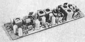
Fig. 4
When adjusting the currents through the transistors kaskadnykh amplifiers set equal to 4…6 mA the selection of resistors R2 and R8. To configure UPCS will need a meter response. for example X1-48. First, before installing the coils L4 - L6, the conclusions of 13 and 12 of the chip DA1 connected through a resistor 75 Ohm. On pin 13 through capacitor of 0.01 ICF serves the output signal X1-48, and its low-frequency input connected to the output UPCS. Rotating podstroechnik coil L7, to ensure that the middle of the S curve coincides with the frequency of 31.5 MHz. Then, after installing the coils L4-L6, feature signal X1-48 to the input UPCS, a detector head of the device is connected to the output 13 of a chip of DA1 and by changing the inductance of the coils L1, L2 and L4-L6, we achieve maximum gain at a frequency of 31.5 MHz. Finally set up UPCS, feeding the signal from the generator frequency-modulated signal, for example G4-70.
Authors: V. Bogdanov, V. Pavlov; Publication: N. Bolshakov, rf.atnn.ru