


")

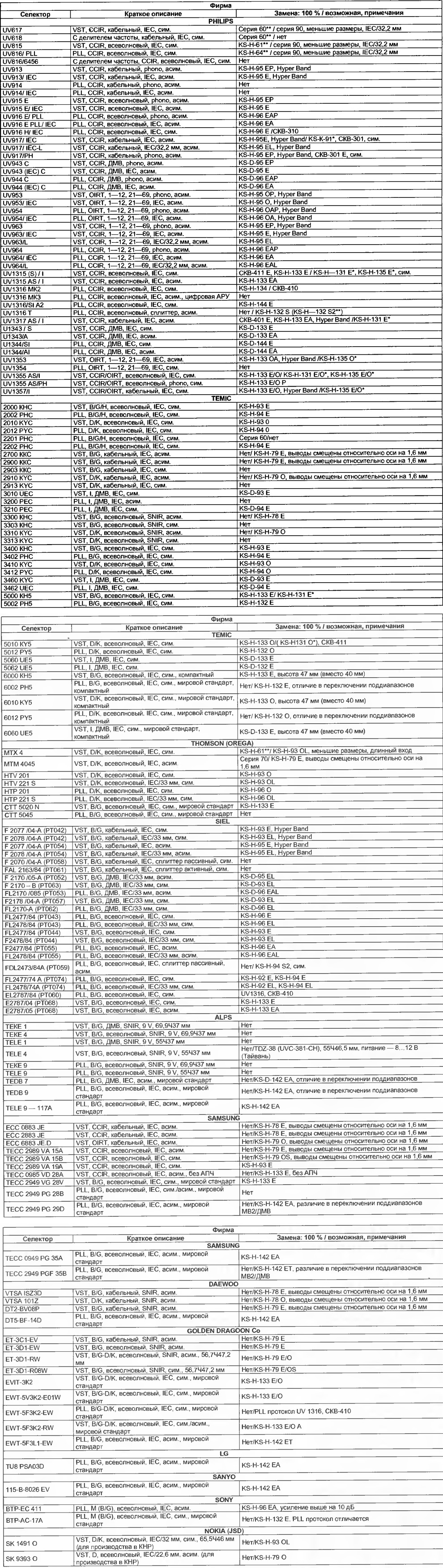
In the repair of professional video equipment repairmen and hobbyists sometimes you may need to replace the selector of the television channels. Pick up replacement can for are presented in table different selectors foreign firms, which lists their main characteristics and possible replacement.
(click to enlarge)
Modern selectors television channels leading manufacturers PHILIPS, THE 1C, SIEL, etc. is not always available, and their cost is relatively high. At the same time JSC "SELTEKA" (Kaunas), JSC "Minsk instrument-making plant" ("Belvar", Minsk) release of a universal model selectors high quality that can replace the models mentioned above firms. Published here the table contains some information about known (to the author) models selectors leading manufacturers, listed their full counterparts (substitutability 100 %), and other possible replacements for the models listed AO. In addition, brief descriptions of corporate selectors can determine their interchangeability. In the graph substitutions marked with a single asterisk selectors that are not yet released due to the lack of orders, while two asterisks - old model, taken from production.
Although the table does not have the electrical parameters of the selectors, they are considered in the selection full analogue and possible replacement. Such basic electrical characteristics, such as gain (within 35…42 dB non-uniformity Frequency response from 2 to 5 dB) and noise figure (7…9 dB MV and 9…11 dB at UHF), for different models of selectors, a large scatter is observed. Therefore, when the selection of analogues they aren't particularly important. As for other characteristics (selectivity FD, selectivity mirror channel, depth adjustment ARU and others), they differ significantly when comparison of different models. Often, however, one model differs from the selector the other is just a standard TV. Equally important constructive characteristics of selectors: the frame size, the pitch between the pins and their numbers, the design of the antenna Jack and the variation of the output of the inverter. These were the main criteria analog search.
In the list of models for each company in the table first lists the selectors with supply voltage 12 V (model company ALPS - 9 IN), and then 5 V.
The short descriptions are the main characteristics in a specific selectors okay. Here we used the notation adopted for selectors [1]. The first presents a method for tuning to the channel used in the model selector: VST - voltage synthesis; PLL - frequency synthesis.
Then follows the standard (system) television, which determines in the end the first inverter signals of image and sound at the output of the selector. For Eastern European participating countries OIRT (including Russia) had adopted the standards D and K, which completely identical, only the standard D apply from 1 St to 12-th channel and K - for ranges, Hyper Band and UHF. In Western European countries the CCIR (systems B, G and H). Learn more about the standards and systems television is told in [2].
The following characterization of the selector - type in the accept band of frequencies: cable, all-wave or UHF only.
Then described the design of the antenna jacks: phono - provides the use of an adaptor cable between the input selector and socket "ANTENNA" TV; IEC (SNIR) is intended for direct connection antenna cable. When the length of the slot equal to 14.5 mm. for brevity, additional information is omitted. For longer nests using a slash indicate their length.
On the characteristics of the output of the inverter selector: SIM. symmetric, Asim. - asymmetric.
In some cases, given in parentheses under the series (frame size) the selector and its analog. For older models of selectors, such as UV617, UV618, UV815, UV816, MTH full analogues can only be called selectors series 60 (KS-H-61, KS-H-64), but they discontinued [1, Fig. 3 a, b]. In this if possible substitute can be the model 90 series, whose body is shorter however, the socket need to choose a long.
For tables it is possible to trace a notation system models some selectors firms. So, for PHILIPS it begins mostly letters UV only some blocks UHF designate one letter U. they are followed by three (or more) figures - series and serial number of developments. The first figures 6-9 reserved for models with power supply 12, and 13 - for models with a voltage power supply of 5 V. number of development in the last two digits characterizes type: even - PLL, odd - VST. However, some models may contain the abbreviation PLL. This is followed by design features: PH/1 - antenna connector PHONO or IEC. For the last length of 32.2 mm insert the letter L. In the symbol selector with 5 V supply voltage in the design features reflected PLL option Protocol, symmetric (S) or asymmetric (A) output, the splitter (T) - distributor and other constructive (and circuit) differences.
The designation of the firm selectors TEMlC consists of four digits: the series (two digits) and number of development. Followed by letters. The first of them To denotes a selector with the synthesis of voltage (VST), P is the selector of the frequency synthesis (PLL), U - selector VST UHF range. The second letter defines the bandwidth the received frequencies and the standard (system) TV: K - system B/G, H - system B/G/H (usually all-wave), Y - system D/K, E - decimeter I. Differences in the antenna input and if output is not provided. For models with supply voltage of 12 V is placed With the last letter, and for pyativoltovom selectors - figure 5.
Key selectors JSC "SELTEKA" considered in [1], but due to the development of new universal models should complement it. In the end, after specify the standard (system), add the letters A - asymmetrical if output and P - antenna PHONO Jack (balanced output and an IEC socket not specify).
It should be noted that the selectors with a 5 V supply, made by a new the world standard for the unification of structures (11 pins with a pitch of 4 mm), have a high degree of interchangeability, which could be even higher if wouldn't the difference PLL control protocols.
The greatest difficulties arose in the selection of analogues and possible replacement of the PLL selectors, which are managed by original software manufacturers (recorded in the processor control), as a common standard does not exist.
The author is grateful for the assistance and courtesy of material specialists AO SELTEKA" J. Mikolaitis and D. Lysene.
Literature
Author: A. burkovsky, St. Petersburg