Applying antenna booster, you can improve the reception quality of the television and radio programs on the border of the zone of reliable reception. Offered in article version of this amplifier has a significant advantage - on signal the cable is fed not only voltage, but also provides restructuring operating frequency of the device.
To improve the quality of TV picture and sound, or sound broadcasting stations have to use directional antennas, and antenna amplifiers. When receiving weak signal remote telecentre and availability powerful signals of local television or radio stations, cordless phones, etc. the broadband antenna amplifiers often do not give positive effect due to overload from nearby transmitting devices.
In this case, help selective antenna amplifiers.
For receiving signals of multiple channels the amplifier has to be tunable. However, if the amplifier near the antenna to rebuild is required single wire that structurally not very convenient. The proposed antenna the amplifier changes when you change the voltage supplied to reduce cable.
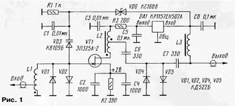
Schematic diagram of the amplifier shown in Fig. 1. This provides improvements in depending on the frequency of 18 (50 MHz) to 14 (230 MHz) dB. It utilizes low-noise gallium arsenide field-effect transistor, which allowed us to obtain high sensitivity. An input circuit formed by the inductance of the coil L1 and by the capacitance of the varicap diode and transistor, provides frequency selection signal and coordination of high input impedance with low output impedance of the antenna. The circuit is tuned by a capacitance change the varicap when adjusting to sue him stress.

The voltage of the stabilized transistor integrated circuit stabilizer voltage DA1. Mode transistor DC set by resistors R2, R3. To align with reducing the cable applied to the coil L2 to the challenge. Diodes VD1, VD2, VD4, VD5 protect the transistor from breakdown of strong signals and interference. The power supply for the amplifier filed by the lead-in cable through the inductor L3.
For adjustment on the amplifier receives a regulated voltage from 7 to 15 In with stabilized power supply unit next to the TV or radio. This voltage is applied to the stabilizer DA1, and a Zener diode VD6 - the varicap VD3. When the power supply 7 through the Zener diode VD3 begins current to flow and is applied to the varicap voltage of about 0.2 V. In this case, his the maximum capacity and the circuit is configured to lower the frequency interval adjustment. With the increase of the voltage on the varicap it also increases the capacitance of the variable capacitor decreases, and the frequency of the input circuit increases.
The overlap factor on the frequency of the input circuit is a little less than two. It means that the amplifier can be used for receiving television signals in the sub-band MV1 (48...100 MHz) or in the sub-band MD2 (174...230 MHz) and for reception only radio programs in the ranges УSW (65...108 MHz). For this change parameters of the coil L1.
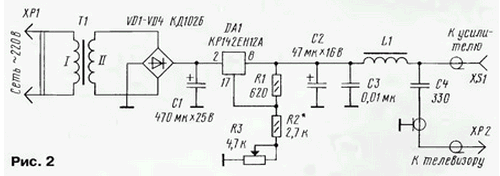
The power antenna amplifier provides a block diagram of which is shown Fig. 2. It was assembled at the integrated adjustable stabilizer. Output the voltage of the block change the resistor R3. Through the inductor L1 it comes to socket XS1, which connect a cable from the antenna amplifier. The received signals from the nest XS1 through the capacitor C4 through the cable plug XP2. It is connected to the input of the TV.

In the amplifier, except indicated in the diagram, apply the transistors APA-2, APA-2 or similar, the varactors SW109А, SW109В, SW109Г, SW122А, SW122Б, SW122В, Zener XA, diodes KDA, KDA. The resistors are preferably used compact: P1-4, P1-12 or MLT. Capacitors are better to use caseless K10-17B or hull of a compact with the conclusions of minimal length.
Coils L2, L3 are wound wire sew-2 0,12 ferrite rings Khj,5 permeability 600...2000. Coil L2 contains 10 turns in two twisted wire (after winding one wire is connected to the other end and get average output), the coil L3 is 15-20 turns of a single wire. Coil L1 wound wire sew-2 0,9 mandrel with a diameter of 5 mm. If the coil has 11,5 loop (removal from the third round), the interval adjustment - 48...92 MHz if 6,5 loop (removal from the second round) - interval 65...110 MHz, but if 3.5 coils (removal from 0,3...0,5 first round) - 150...230 MHz. For small movements interval reconstruct-ing towards higher frequencies slightly pushing the coils coil.
The power supply can be applied polar capacitors C50, nonpolar K10-17, KD or KT, variable resistor - STRs JS4, constant MLT, S2-33. The inductor L1 is similar to the inductor L3 in the amplifier. The transformer needs to provide the AC voltage at the secondary winding of about 15 V.
The establishment of an amplifier is to install the required range of adjustment the selection of the number of turns of the coil L1 and the bandwidth of at least 7 MHz change space allotment. In the power supply of the selection of resistors R2 and R3 set the interval of variation of the output voltage. When the excitation amplifier at high frequencies at the output drain of the transistor need to put ferrite ring ("bead") or to apply the glue (epoxy glue) the core of carbonyl iron powder.
All the details of the amplifier are placed on the PCB of bilateral foil fiberglass. The location of the traces shown in Fig. 3. Second the left side of the Board metallized, in addition to these, the dashed line cut the input and output pads, and foil connected with the common wire first side through the circuit. After installation and establishment of field-effect transistor pour a drop of epoxy glue, a fee close with side parts metal cover-screen cover for the device from all sides protective a layer of water-resistant paint or varnish.

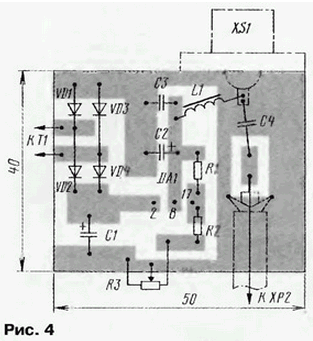
Details of the power supply unit is mounted on a circuit Board from unilaterally foil fiberglass, printed conductors is shown in Fig. 4.

The amps can be switchable, for which you will need to add two relays, including them in accordance with the scheme in Fig. 5, then when you turn off the supply voltage antenna will be connected directly to the lead-in cable, bypassing amplifier. You can use relay RES-34, REC-43 with a voltage positives about 6 V. the fees will have to increase, and the wiring conductors change a little.
Author: I. Nechaev


