Application amplifier with high selectivity can dramatically improve reception signals are UHF stations and will eliminate interference from neighboring closely spaced stations. The basis was taken the unit SC-D-1, which was used in tube-semiconductor the TVs.
Simple alteration of SC-D-1, which can to perform even a novice Amateur radio operator, allows receive amplifier UHF signals with good operational characteristics:
- Work frequency range, MHz ....................... 470 - 790 ( 21 - 60 channels)
- The coefficient gain, dB, ...............................20
- Irregularity Frequency response, dB, not more.................4
- Voltage power stable, In ... + 12
- Consumed current, mA ...................................... 15
To the advantages of such an amplifier include high selectivity, significant the suppression of interference on adjacent channels. There is a disadvantage - calls for restructuring ( turning rotor ) at switching to another channel. However, if done reception on one UHF channel, the need to restructure no.
Briefly consider the original scheme SC-D-1.

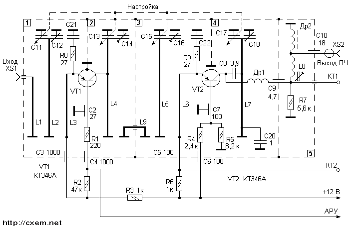
Fig. 1
In the first the camera is first the stage unit, which is made on the transistor T1, which works in boost mode with ABOUT. The resonator L1 provides coordination of input to the antenna, L2 with capacities C11 and C12 forms perestraivanie input circuit to tune to the desired channel. The collector of transistor T1 loaded the contour L4 C13 C14, located on the second camera. Next, the signal passes the contour L5 C15 C18, located in the third camera. Thanks the inductance L6 signal falls on the emitter the transistor T2. Transistor T2 is assembled RF Converter signal in the if TV. The transistor T2 is connected to the circuit capacitive treatacne, load cascade is DR1, which together with C17,C18,C8,L7,C20 located in the fourth chamber.
Alteration SC-D-1 is as follows:
- as in real conditions first cascade transistor T1 controlled AGC system television receiver, you need to install the usual, without AGC, the mode of operation by the introduction of the voltage divider two resistors ;
translation the second cascade transistor T2 mode conversion in amplification regime that is obtained by removing several elements.
Before how to get started, it should be remembered that to handle the unit needs carefully, because the slightest changes in the location of details if you're not careful disassembly can be the cause of detuning circuits with resonant circuits.
So, removing spring bar at the top cover, carefully remove the cover. Account cameras ( there are only 5 ) is carried out starting from the nest antenna input. Carefully inspect the internal wiring. Inside there should be explicit damage - burnt and broken resistors, capacitors. During the rotation handles Vernier mechanism the movement of plates Quad capacitor should be free, without the closure plates between them or with other elements. When operating the unit cannot to change the position trimmer capacitors made in the form silvered plates and located in front of sections the variable capacitor, and also resonance lines, made in the form silver-plated tires and segments wires.
Carefully vypayayte the following elements:
- C8, C20, DR1 - located in the 4th the chamber;
- L8, DP2 and R7 is located in the 5th camera. The resistor R7 in some copies of SC-D-1 may be absent.
Further you must determine the brand transistors that are in Your block SC-D-1. The fact is instead of transistors, indicated in the diagram Fig.1, can to be other, for example AF-239 and AF-139, which are analogs of transistors and GTA GTB respectively. If as T2 is set transistor GTB or AF-139, have to remove and replace GTA. Transistors of this type employed in all blocks SC-D, as well as in blocks SC-M e configuration, so that in principle to find such a transistor is not difficult. Before installing new transistor should check. If the test is made with an ohmmeter, should remember that the voltage ohmmeter may exceed valid return the emitter voltage transition. Therefore, defining the serviceability of the transistor the ohmmeter should not use a low-impedance the limits of the ohmmeter. If there is choose from several transistors, you should choose a transistor with possibly more h21e.
Before install transistor should the General conclusion ( "corps" ) to connect with soldering the body of the transistor. Above the camera window in which is the transistor, can is cut slim silver plated wire. This a segment is a "tail" L6. Therefore in any case not try to remove it by desoldering. Because warming can to change the position in L6 the space, which will lead to the detuning circuit. Remove can be done, biting off the "tail" side-cutting pliers. Cabinet output transistor T2 can be put in a small the hole that is available under resistor R8 and unsolder it from side 4-th camera. Conclusion header to be soldered in the same point on L7, which was soldered conclusion withdrawn of the transistor. Caution solder the findings of the emitter and base without overheating places brazing, soldering as in places capacitors are small capacity, which in case of overheating can collapse.

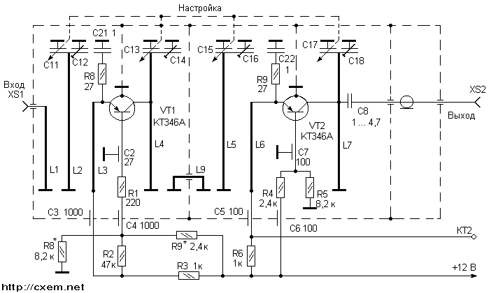
Fig. 2
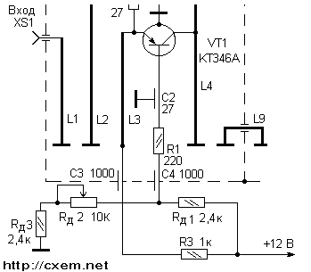
Further you need to remove the resistors R6 and R4, thus disabling the second cascade from the food chain. Then you must perform the installation of resistors Rд1, and Rд2 Rд3, as shown in Fig.3.

Fig. 3
Install the engine resistor Rд2 in average position. Connect voltage +12 volts at the map rotation engine resistor Rд1 set voltage +9.5 In on the emitter and +9 on the basis transistor T1. Then turning off power, measure the total the resistance of the resistor and Rд2 Rд3. Choose the resistor type MLT-0,125 par value, close to measured and set it as a resistor R8 in Fig.2, Rд1 will remain in the scheme as R9. In the scheme apply power, and control the voltage across the terminals transistor T1.
Work the first stage can check visually in the image on the screen TV. For this tune the TV to one from the UHF channels, which accepted with bad quality. Then turning off the antenna cable from the entrance the TV connects it to the input of the amplifier. Cut cable RK-75 with soldered on one end plug connect the input of the "UHF" TV. Braid another ends of the cable are soldered to the the amplifier, and Central vein through capacitor 4.7 pF. solder in place the desoldering output collector of the transistor T1. Although the point of maximum the signal is closer to L4 the case, you should not pripisivaetsya in those places where there is no factory soldering, to avoid the deterioration the parameters of the circuit.
Include the amplier smooth the rotation of the Vernier mechanism configured to images screen. The image should to be the best in quality compared to what it was before the inclusion of the antenna through amplifier. Then check the operation of the circuit L5 C15 C18. For do this by turning the power off and hotpaw "control" cable from L4, fluster him to the place connections L5 and C15. Again turn on the power amplifier and control signals for the image quality in this case should not be observed deterioration image.
Setting the second cascade is similar. Turning off the power to the amplifier, solder the resistor R6, and instead of the removed resistor R4 set trimpot, the nominal value of 5.1...10 kOhm, and install it in the engine the middle position. Then "control" cable through the capacitance of 4.7 pF to fluster the soldering point of the collector transistor T2 and include food. Smoothly rotating engine resistor achieve the set-up transistor T2 with the same value as at T1. Then remove the power measure the resistance the variable resistor and solder a resistor instead MLT with a face value of close to measured. In conclusion remove the nest CP1 and pass capacitor C9. In the openings put the cable RK-75, which will connect to TV. The braided cable raspalaut "body", and Central vein through the capacitor C of the L7, picking up the soldering point of the experimental by, at the best quality image.
Amplifier can be enclosed in any favourite decorative body. If the amplifier is be used on multiple channels it is convenient to do at the case marks the desired channel, and the knob at risk.
And in the conclusion about further improvement.
The author is not considers appropriate for increase the sensitivity enable to log device broadband amplifiers, because of the uneven frequency response and big noise such devices can dramatically to decrease the quality of reception on high frequency or even all channels. Good the results can give the inclusion of one or two-stage broadband amplifier after the release of this amp. In this case have carefully to align the input/output of both amplifiers.
Author: V. Sinitsky; Publication: www.cxem.net


