The kit to receive satellite TV programs includes a parabolic antenna, which is installed so that fell into the line of sight from the satellite, a step-down Converter and the tuner (indoor unit). Among themselves they are connected by coaxial cable, the length of which should not normally exceed 15...20 m, but in practice sometimes more. As a result, the signal arriving at the tuner, is considerably weakened, and the quality of the image deteriorates.
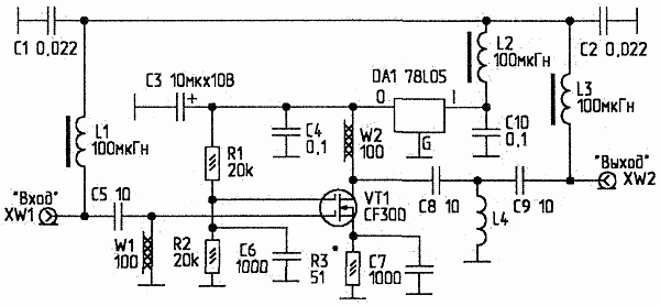
To compensate for the attenuation in the cable offering the main amplifier (Fig. 1). It is powered by the injected into the cable voltage and turned on in the middle of the cable. The amplifier is assembled on a single stage scheme, its gain is at least 10 dB. It is built on dfugstore low-noise microwave field-effect transistor. Voltage stabilized low-power IC DA1. LPF L1-S1, L3-C2 prevent self-excitation of the amplifier and provide passage to the Converter supply voltage. 
Fig. 1. Schematic diagram of the main amplifier
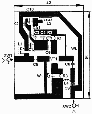
The amplifier is collected on a printed circuit Board (Fig. 2) from foil fiberglass 1.5 mm thick. All the details - SMD or the normal day, with the minimum length (to reduce parasitic inductance of the leads). XW1, XW2 - connectors, F-type. L4 has 2 turns of wire PMTL-2 d0,36 mm, wound on a mandrel d2 mm, which is removed after winding.

Fig. 2. The printed circuit Board
The amplifier is placed in a brass or cast zinc aluminum casing. Case after setting the seal. VT1 can be replaced by domestic PA-2 (parameters of the amplifier should improve, but this transistor is very difficult to find). When setting up, might have to pick up the resistor R3 by the maximum gain of the device as a whole.
Author: V. Fedorov, Lipetsk; Publication: www.cxem.net


