In the technique of cable television (CATV) widely used power dividers (splitters) signals. They are used for external and internal wiring networks KTV and have a different configuration. Typically, the power applied to the input of the divider, evenly distributed between multiple outputs. However, there is a separate class of divisors, called taps, which otvetst part of the power transmitted via the trunk cable.
The diagram in Fig. 1 is a wideband divider that distributes the input signal between the N outputs. The attenuation factor of the signal K3 on any output is calculated by the formula
KZ = 20*lg(N) (dB). (1) 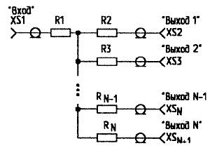
Fig. 1. Broadband divider
As you can see from this formula, the signal on any output is attenuated. If you amplify the signal at the output of the divider to the level input, get active divider, or splitter Constructively amplifier to include the divider, and the ratio of its the gain is chosen equal to the attenuation factor of the divider (SC). The resistors R1-RN are equal and calculated by the formula
 (2)
(2)Resistance inputs and outputs must be equal Zн (load matching).
Table 1 gives the data of the divisor having N outputs, operating at 75 Ohm load. Table 1 No. R1...RN, Ω KZ, dB 2 25 6,02 3 37,5 9,54 4 45 12,04 5 50 13,98 6 53,6 15,56 7 56,3 16,90 8 58,3 18,06 9 60 19,08 10 61,4 20 16 66,2 to 24.08 Zн=5 Ohms
The main advantage of these devices is their output and evenness of frequency response in the passband. In Fig. 2 shows the structure of the divider with three outputs. All resistors have a resistance of 37.5 Ohms. The divider is collected in brass or dural box. Input and output connectors - type "F" or "SMA". The first is preferable, because provide connecting coaxial cables without the use of soldering.
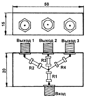
Fig. 2. Design of a divider with three outputs
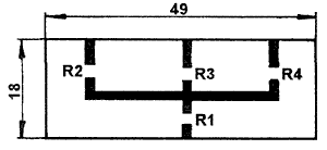
Fig. 3. The printed circuit Board divider with three outputs
Theoretically, the bandwidth of such a scheme unlimited. However, when using the installation shown in Fig. 2, high frequencies (above 800 MHz) frequency response becomes irregular and has a recession (the influence of parasitic capacities and the inductance of the terminal of the resistor).
To eliminate this undesirable phenomenon using Leadless resistors, surface mounting of printed circuit boards. Printed circuit Board (Fig. 3) is made of two-sided foil fiberglass brand STNF thickness of 1.5 mm. track Width - 1.2 mm. the Resistors soldered in breaks tracks. Application of this method allows to obtain excellent results dividers at frequencies up to 3 GHz. When using dividers for higher frequencies, the circuit Board is made of fluoropolymer.
In practice, broadband dividers are used for distribution of signals from the LNB receiver satellite TV programs between multiple tuners (indoor units). To compensate for signal attenuation in the divider is used compensating amplifier.
Schematic diagram of the coupler of the first if signals in the receivers of STW programs is depicted in Fig. 4, wiring diagram, using SMD technology - a in Fig. 5.
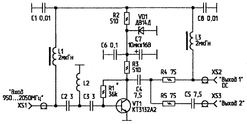
Fig. 4. Splitter first if signals in the receivers STV programmes
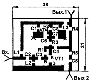
Fig. 5. Wiring diagram of the splitter
Crosses on the drawing Board indicate through holes through which the respective pads are connected with a common bus (second party). General tire has an electrical contact with the housing of the coupler. XS1.. .XS3 "F"connectors. All elements (including L1 and L3) - SMD type (can be used conventional elements, biting fully their findings and soldering directly to printed tracks). Coil L2 is frameless, with an internal diameter of 3 mm has a 4-loop wire PMTL diameter of 0.47 mm.As you can see from the diagram, compensating the amplifier is powered with DC voltage (at the same time nourishing and outer Converter), which is received from the tuner enabled on Output 1. The passage of the supply voltage from the second tuner and oscillations of a frequency of 22 kHz are blocked decoupling capacitance C5. Thus, the leading tuner is the one that connector XS2 "Exit 1".
In Fig. 6 shows a schematic diagram of the divider-coupler, which, unlike the circuit in Fig. 1, has a lower attenuation. Taps are widely used in KTV networks when you access the wiring. The signal from the main cable through the trunk the coupler is fed to the entrances cable (thinner than the trunk). On each floor in the cable is included the taps shown in Fig. 6. It does not matter which of the connectors XS1 or XS8 is the input (output).
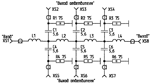
Fig. 6. A schematic diagram of a splitter-coupler
On the top floor, where the end sections of the cable, or install the tap, connect the plug 75 Ohm ("terminator"), or a splitter, shown in Fig. 7.
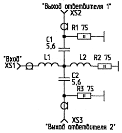
Fig. 7. Schematic diagram of the splitter
Driveways splitters collected in brass or dural buildings of appropriate size. All the inductors frameless, diameter 5 mm. L1, L4 (Fig. 6) and L1, L2 (Fig. 7) - 2,5-loop; 12, L3 (Fig. 6) - 6 turns, wound wire PMTL diameter of 0.8 mm, the winding pitch of 1.5 mm. All connectors - F-type.
For the branch signals from the main cables use taps collected on similar schemes (Fig. 8,9). In connection with the fact that passive components are passed in this case, a higher power, load resistors must have allowable power dissipation of at least 2 watts. Accordingly changed the type of connectors through which the coupler is connected to backbone cable. As XS1, XS2 use of microwave connectors type SR-75-66FV. Coils L1, L2 are wound with wire PMTL the diameter of 1.2 mm (specify when you configure the step of turns).
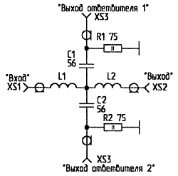
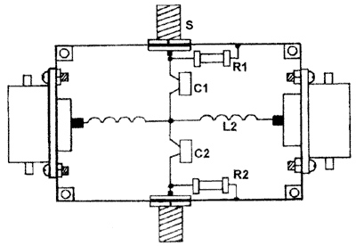
Fig. 8,9. Trunk taps
In principle, it is possible to produce pipeline taps with arbitrarily large amount of outlet outlets, however practice enough to have two taps. At the end of the trunk cable set or coupler (Fig. 8), to the exit which connects 75 Ohm terminator, either a splitter (Fig. 7). Described couplers work well at frequencies up to 300 MHz and quite well - in the range of 300...800 MHz. If sections of the coupler is used for routing the signal from collective UHF or MMDS antennas, which have an external amplifier and Converter, on floors install taps, depicted in Fig. 6, and at the end of the splitter cable-power injector (Fig. 10). Inductance L1 ...L4 are identical used in the scheme in Fig. 6. L5 and L6 - type D-0,1. As a T1 use any small transformer with an output a voltage of 15 V and a maximum voltage 0,5...0,7 A. the Device is assembled in dural casing; elements of power supply separated from the circuit fan-out partition. DA1 is attached directly to the body, playing the role of a heat sink.
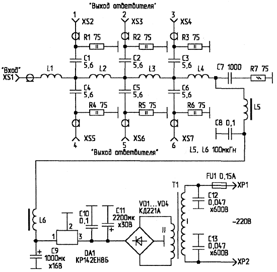
Fig. 10. A splitter injector power
In Fig. 11 depicts a typical wiring diagram of signal from one MMDS antenna (2,5...2.7 GHz) [1]. As the feeder cable use RG-6U, subscription - RG-6. When debugging a system, you must specify the required voltage of the Converter MMDS. If it is 12V, you need to replace DA1 (Fig. 10) corresponding to (e.g., for PI=15 is used In CREW).

Fig. 11. Wiring of signal from one MMDS antenna
It is impossible to ignore the class of devices called "combiners-splitters" STV/TV signals. Their principle of operation is illustrated in Fig. 12. The combiner sums the signals PC STV Converter (frequency band occupied by the signal - 950...2050 MHz) and amplified antenna amplifier from MB and UHF TV programs (48...800 MHz). The resulting signal on the lead-in cable is supplied to splitter-splitter, where once again stand out from PC STV (served on STV tuner) and MV/UHF-TV signals (served on the antenna input of the TV receiver). In Fig. 13 is a diagram of the combiner. XS1 XS3..."F"connectors. The circuit is mounted in duralumin enclosure. Inductance - frameless, d2,5 mm. They wound silver plated wire d0,31 mm and have: L1 - 2 coil, L2 - 3 turns, a L3 - 2,5-loop.
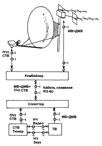
Fig. 12. The principle of operation combiners-splitters
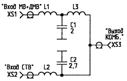
Fig. 13. The combiner circuit
Antenna amplifier MV/UHF is powered by a DC voltage coming from STV tuner. The current consumption of the amplifier should not to exceed 50...70 mA.
In Fig. 14 shows a diagram of an active splitter, which splits the signals combined by the combiner, and also compensates for the attenuation introduced by the divider, which is part of the splitter. The compensating amplifier is powered by STV tuner via cable reduction. L2 and L3 - frameless, d3 mm silver plated wire wound d0,31 mm and have: L2 - 3.5 coils, a L3 - 3 turns respectively. The splitter is mounted SMD-method and consists in brass or duralumin case.
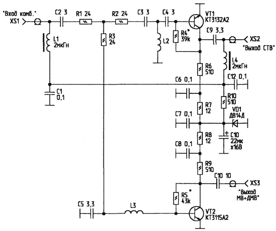
Fig. 14. Scheme active splitter
In conclusion, it should be noted that when setting the above-described devices it is desirable to use sweep with band swing from the 30 to 3000 MHz. After setting up devices, you must remove their accurate frequency response and put them on the top cover of the device, for visual representation of the characteristics of the schemas used.
To avoid the risk of floating potentials necessary to provide grounding of the case of the described devices.
Literature
Author: V. Fedorov, Lipetsk; Publication: www.cxem.net


