Operated by Amateurs whip antenna (Ground Plane), as a rule, have a very high VSWR of up to 3, require bulky supporting porcelain insulator. Tuning of the antenna is in resonance to the middle of the selected range, is carried out, usually by shortening or lengthening the vibrator from the calculated or presented in the descriptions of the variables.
The described antenna is free from the above drawbacks, easy to configure, does not require a bulky support insulator and has an extremely low VSWR (1,2-1,04 with careful tuning of the antenna); that is, provides a good matching of the antenna with feeder and the output of the transmitter.
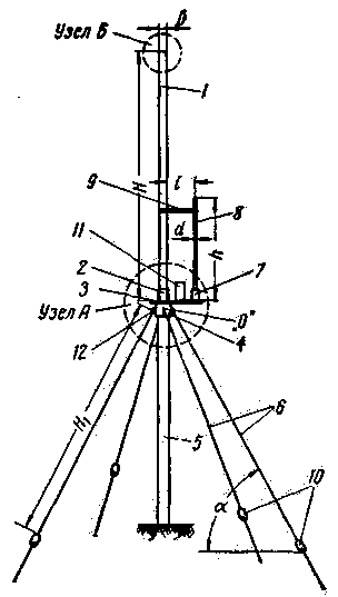
Whip antenna with gamma-matching unit 20-meter range (Fig. 1) represents the vibrator 1, screwed into the coupler 2, the latter in turn is welded to one edge of the metal pad 3. The material for the vibrator 1 is almost indifferent. So UA1NX and UA1OQ as a vibrator applied ordinary tap galvanized pipe 3/4". To the lower plane of the platform 3 on the same axial line with the clutch 2 is welded to the second coupling 4 of larger diameter under the mast 5. This sleeve also has an internal thread, where virtuves the mast 5.


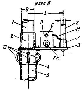
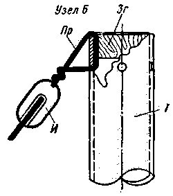
Fig. 1. General view of the antenna: H=H1=5 m 12 cm; l=100-250 mm; h=1800 mm; a=45°. The node "A": 1-vibrator with a diameter of 33 mm; 2 - coupling EXT. thread; 3 - Playground 250x60x5 mm - material St-2; 4 - coupling EXT. thread 5 - mast; 7 - the reference insulator; 8 - tube diameter of 10 mm; 11 - metal box; M - wire "magneto". 12-lugs for attachment of the counterweight 6. Node B 1 - vibrator; 3G - cover; And the insulator; Ol - copper wire with a diameter of 2 mm.
To the coupling 4 are welded four lug 12, which when assembling the antenna attached four beam - counterweight H1 ending Marinova insulators 10. Balances H1 are both guyed masts of the first tier. On the opposite from the end of the vibrator pad is attached a small support insulator 7, which at its lower end the tube is gamma-Aligner 8. The pipe of the vibrator 1 and the tube gamma-Aligner 8 covers the metal bridge 9, to which the antenna can move freely up and down.
On the upper plane of the platform 3 between the vibrator 1 and the gamma-Aligner 8 is installed and permanently fixed metal box 11, which are pre-mounted variable capacitor with handle derived under the "slot" and the high-frequency connector. As the capacitor C1 is very well suited trimmer capacitor from the HRC receiver SWМ. Since the maximum capacity of this capacitor Raina 100 PF, parallel to solder the capacitor capacitance constant 50-60 PF type CSR (Uраб-500). The stator and rotor plates of the capacitor C1 must be isolated from the metal box.
At the upper end of the pipe of the vibrator 1 are drilled four holes at 90' on the circumference, which are inserted segments of copper wire,they are bent over the edge of the tube. Thereto is connected to the antenna insulators, and then through the segments braces length of 70-90 cm strung insulators used for antennas, thus formed the second tier of guys. The top opening of the pipe of the vibrator 1 is closed by a wooden plug plug 3A, which prevents the penetration of moisture inside the pipe vibrator. The upper end of the tube gamma - Aligner is also closed by a flap, which is used for the same purposes.
To high-frequency connector, mounted on a metal box 11, connect the coaxial cable with a characteristic impedance 72-75 ω (RK-1; RK-3) or, preferably, a cable with a characteristic impedance of 60 to 65 ohms (RC-6).

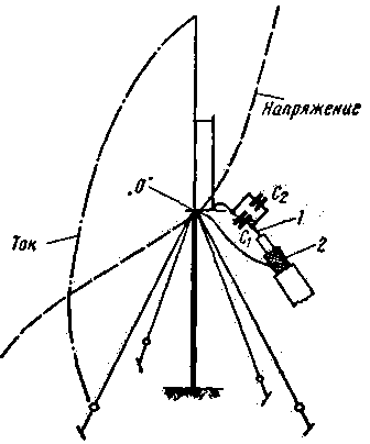
Fig. 2. Diagram of distribution of current and voltage
in whip antenna and the connection circuit coaxial cable:
1 - wire cable; 2 - braid cable.
Insulated contact RF connector is connected to the stator plates of the capacitor C1, and to the rotary plates podpisyvaetsya segment of flexible conduit with reliable insulation (type "magneto"), this segment is output through the hole in the box 11 and soldered to the base of the tube gamma-Aligner 8, in place of its attachment to the supporting insulator. As can be seen from Fig. 2 point 0 is the zero point of the potential, hence the danger of breakdown of the capacitors C2 and C1 are excluded; this point through the screen of the coaxial cable is connected to the chassis of the transmitter.
During the construction of the antenna on a 10-meter Amateur band all sizes must be reduced in two times except diameter pipes (their ratio) and the distance l between the center lines of the pipes.
The angle of radiation of the antenna to the horizon is about 15°.
Adjusting the antenna can be made using the gear, the device for determining the SWR and field strength indicator. The simplest and most efficient way of setting up the antenna is effected by the inclusion of a thermal ammeter (3 A) to break the wire coming from the rotary plates of the capacitor C1 to the base of the tube gamma-Aligner. The feeder is connected to the antenna through the RF connector. Served RF voltage to the antenna via a cable. Originally jumper 9 is installed at a distance of 170 cm from the site and the rotation of the plates of the capacitor C^ achieve the greatest possible deflection of the ammeter. Further, by moving up or down jumper 9 and each time adjusting the capacitor C1 achieve the maximum deflection of the ammeter. Obviously, when you configure the antenna must also tune the transmitter to the greatest radiation exposure. Setting transmitter and antenna should be in the middle of the Amateur range. When the ratio of pipe diameter of the vibrator to the diameter of the tube gamma-Aligner 4:1 SWR of the antenna, and therefore, the detuning of the antenna at the edges of the range does not exceed 5% of setting it in the middle of the range. In the transmitter with a power output of 200 watts hand thermal ammeter should deviate to 1.8-2.2 A, the SWR of the antenna if you are using cable RC-6 is equal to 1.02-1,04, cable RK-1; RK-3 and 1.05 to 1.09. After the final adjustment of the antenna on the highest radiation jumper 9 is tightly secured, its girth tubes vibrator Aligner and coated with clay. Hole slot of the capacitor C1 is closed (for example a spinning disk) and coated with clay.
The described antenna is operated at UA1NX since March 1962 and showed good results.
Typically, the signal strength at work on the above-described antenna is estimated at 2-3 points higher than when working with horizontal polarization antennas.
Author: K. Vinogradov, (UA1NX), Severodvinsk; Publication: N. Bolshakov, rf.atnn.ru


