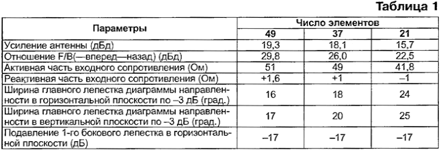
Once upon a time radio Amateur DL6WU suggested that successful design 49-element antennas "wave channel" range 23 see This was before wide use of computer programs for modeling antennas. I laid these this design into the program MMANA, slightly corrected them and received a very good results are summarized in table. 1.

Calculations were performed for a frequency of 1296 MHz. As shown by the results in the simulation, it was possible to perform the antenna in three variants: 21, 37 and 49 elements, without changing the length of the elements and the distance between them. Different will only traverse length: 4.1 m (49 items), 3 m (for 37 elements) and 1.5 m (21). And what is most important and enjoyable - active the input impedance of the antenna in all three cases close to 50 Ohms, and reactive negligibly small. This gives you the opportunity to directly connect a coaxial cable with a characteristic impedance of 50 Ohms to the active vibrator.
As an active used a simple split vibrator copper wire diameter 3.2 mm (length - 112 mm). Good quality cable and minimum the length of his findings when soldering to the vibrator - only here and quite important requirement.
As an active vibrator could be applied classical loop dipole with balun U-knee, but it is very doubtful that the gains from balancing will outweigh the losses created by the presence of additional connections. For example, say that the measurements of even a simple "pulling up" HF connector SR-50-164 leads to a change in the SWR at this frequency, and what can we say about additional brazed connections....
Antenna gain can be increased by a further 0.5...0.6 dB, but it requires more substantial processing of the antenna and is associated with a decrease in input resistance up to 20...30 Ω, which again raises the need for more coordination and, as a consequence, additional connections.
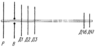
The antenna design. Schematic representation of the antenna (without respect geometric proportions) is given in the figure. Letters marked: R - reflector, - active vibrator, D1... D - Directors.

As the carrier traverses used dural (D16T) tube diameter 14 mm (49 in the embodiment of the elements she redstavlena another tube with a diameter of 12 mm for the last of Directors). All items (except the active vibrator) made from duraluminum wire with a diameter of 3.2 mm. Elements skipped through traverse through insulators, which served as external segments tubings (normally black) coaxial cable with a diameter of about 4 mm Do it so:
1. Choose the diameter (type) coaxial cable so that the segment taken from his isolation 2,5...3 cm with worn friction element.
2. In trial a (mock) segment of the tube (the same kind you will be used to traverse) drill a through hole, the diameter of which is selected so that the insulating tube being removed from the cable, the friction was held in the hole and a little acted on both sides of it.
3. Securing the tube with a threaded through hole insulation in the grip, slide, turning, element as far as possible in isolation, and then light strikes hammer punch element through the insulation and the yoke, trying not to move the insulation. Sometimes insulating tube is pushed out of the hole in traverse - then the operation must be repeated. To facilitate this process and reduce friction of the element edge preliminary round out a bit with a file and moisten the element of water. In the end, the centering element in traverse, tapping his a hammer with one side or the other.
Fixed so the element must be firmly fixed in traverse so to shift it manually, it was quite difficult. Active vibrator fix on a small plate of fiberglass.
The described technology is the installation of the elements used by many ultramarathoning, good, by the way, and for YAGI antennas bands 144 and 432 MHz. Its main advantage - no galvanic contact elements with traverse, which is often the cause galvanic corrosion, deteriorating the antenna parameters.
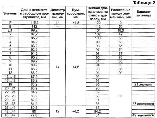
However, the element mounted in the yoke thus, requires some correction of its length compared to the length in free space, usually used in calculations by computer simulation. Therefore, in table. 2 the two lengths of elements: given (full length of the element through the yoke) and excluding (element length in free space) boom-correction (+ 4.8 mm for a beam with a diameter of 14 mm and + 4.2 mm for a beam with a diameter of 12 mm).

Cutting elements to produce as accurate as possible, otherwise specifications the antenna will be worse than shown. All the design data of the antenna shown in table. 2. If elements is used for wire (tube) or other diameter the diameter of the tube beam differs from that specified, the length of the elements must be adjusted.
A 49-element embodiment, the assembled antenna is a bit slack, so it is advisable to apply stretching, supporting the yoke, for example, from the line.
The antenna of the 49 entries in the competition "Field day" managed connection a distance of 650 km.
Author: Nicholas butchers (UA3DJG), Ramenskoye, Moscow region.


