


")

The difference between this antenna from similar multiband GP who tune in to the operating frequency matching unit located at the base of the vertical radiator is the absence in this block of the switching elements or elements with variable parameters (capacitors, inductors). Such a solution reduces the probability of failure of the matching block from exposure to adverse weather conditions, increases the reliability of the antenna as a whole.
This article discusses antenna that can be placed on the roof of the Elevator shaft of a multistory building. It is intended for use on Amateur radio stations who have separate or built-in transceiver interface box that allows you to work without reducing power to a load with a VSWR less than 3. This antenna has neprestavejme matching device providing the specified level of harmonization in the most part of six Amateur bands (7-21 and 28 MHz). Matching device installed at the base of the antenna.
Antenna (Fig. 1) is a vertical emitter - pin height of 6.25 m To 1/S of its height it is made of steel pipe with an outer diameter of 114 mm, and the upper 2/3 of the pin to reduce its weight and sail area of the antenna is made of four parallel steel pipes with a diameter of 40 mm (equivalent radius the same as the bottom of the pipe). The emitter is mounted on the supporting insulator. In practical design was used steatite insulator model SB-S.
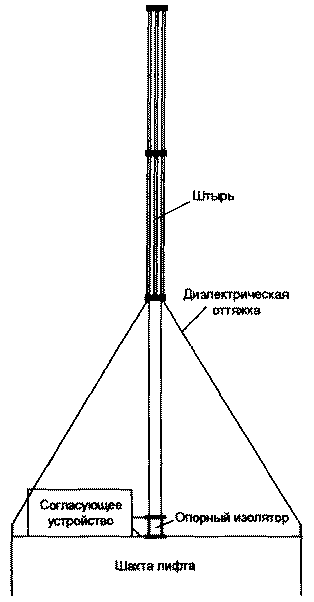 Fig.1
Fig.1
The antenna has a dielectric of a delay, the lower ends of which are fixed to the edges of the roof of the Elevator shaft, and the upper - the upper end of the pipe (approximately at the level of 1/3 of the height of the antenna). The counterweight is made of eight steel strips of a width of 180 mm inscribed in the size of the roof of the Elevator shaft 2,5x2,5 m (Fig. 2).
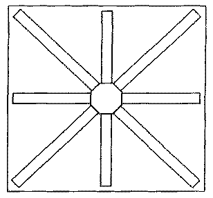
Fig.2
Antenna weight - 58 kg In table. 1 shows the measured input impedance and VSWR of this pin on the various Amateur bands (wave impedance of 50 Ohm feeder).
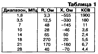
On the ranges of 1.8 and 3.5 MHz antenna emits almost no, and most of the other bands own SWR is too high for its effective operation. The problem of matching the antenna with feeder solves neprestavejme matching device WHICH is schematically shown in Fig. 3.
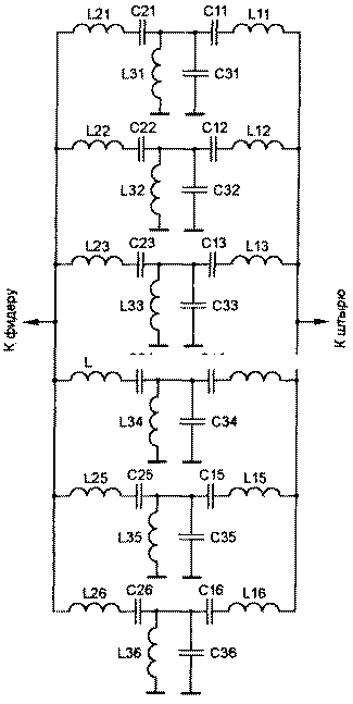
Fig.3
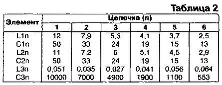
The calculated values of circuit elements are given in table. 2 (L is in µh, C in PF).
In circuit elements matching device developed significant currents and voltages, so here it is desirable to use ceramic capacitors CU-1 and single-layer cylindrical coil of copper tube or wire of a large diameter. The coils should be possible to adjust the inductance value ±20% (for example, by means of a movable clamp). The size and power of the elements chosen depending on the transmitter power, which will be used for the antenna.
The node matching is performed as follows. In each of the six chains are consistent input impedance of the antenna with a characteristic impedance of the feeder to the average frequency of the corresponding band (the first chain at the frequency of € 7.05 MHz, etc.). Coordination is performed as if the G-shaped link (direct or inverse, depending on the size of the active part of the input admittance of the antenna at this frequency) containing inductance in sequential branch and capacitance in parallel. Actually these inductance and capacitance are obtained by increasing L1 n or L2n and FFP contours L1nC1n, L2nC2n, L3nC3n, initially configured to resonate at an average frequency corresponding range (ranges from 1 to 6 depending on the range) the Purpose of these outlines is to weaken the mutual influence of the chains to each other so that it was possible alternate process of harmonization of antennas on different bands.
Matching device works. For example, from the transmitter receives a signal with a frequency equal to the average frequency of the first range. Assume first that the characteristic impedance of chains 2-6 are very high (i.e. inductance them in large and small capacity). In this case, the input impedance of the chains of 2-6 will also be quite large and significant impact on the setting of the first chain will not have. The resistance of the antenna in the first range is less wave resistance of the feeder (50 Ohms), so to harmonise antenna with feeder, you can use the l-shaped chain having a series inductance from the antenna and parallel capacitance of the transmitter. Contour L21C21 tuned in resonance, the resistance is zero, so as its not. In the first chain, the value of inductance L11 more than the value of the inductance L21 by the amount necessary to match the input impedance of the antenna with feeder In parallel branches, the value of the capacitor C21 is also more necessary to configure the circuit L31C31 in resonance by an amount ensures matching of the antenna with feeder. With a slight frequency deviation from the resonant loop resistance L21C21 would be low, and resistance circuits L11C11 and L31C31 will be only slightly different from the values necessary for matching the antenna at this frequency.
In fact, the magnitude of the characteristic impedance of the circuits chains 2-6 cannot be made very large, for constructional reasons, and because of the need to ensure sufficient bandwidth for 2-6 ranges. Therefore, chains of 2-6 affect the level of harmonization. This effect is compensated by an appropriate change of variables L11 and C31.
Job matching device for the other bands similar, except those in which the active part of the input impedance of the antenna is more of a wave resistance of the feeder. On average frequency corresponding range is zero resistance circuit L1nC1n, and coordination is accomplished by changing the values L2n and FFP.
Configuring matching device is made so. First, expose the magnitude of the elements close to the calculated ones, and adjust the contours L1nC1n, L2nC2n, L3nC3n mid frequencies of the respective bands At the same time achieve the minimum value of the impedance circuits L1nC1n and L2nC2n and maximum - for L3nC3n. The quantities vary 1_1n or 1_2n and FFP actually carry out the setting to medium frequency range, and it is recommended that you begin configuration from the low frequency range. Since the presence of contours does not completely eliminate the mutual influence of settings on different bands, the tuning process has to be repeated.
To extend the bandwidth settings (reduce the SWR on the edges of a range) should increase the inductance L3n in the respective chain. To reduce the mutual influence of, on the contrary, it is necessary to reduce the inductance L3n, while maintaining the resonant frequency of the respective circuits. For small values of inductance coils L3n perform it in the form of a plume. It is desirable that the physical size of the items were small.
The setting recommended in the installation location of the antenna. Technically it is not difficult, since the matching unit is located at the base of the antenna. After the position adjustment of the adjusting elements is fixed (e.g. by soldering) and later in the operation do not change. SWR on "resonance frequency" antennas for different bands is in the range of 1.2-1.7 and only on the range of 18 MHz above it is 2.2.
Literature
Radio 11/2000, pp. 63-64
Publication: N. Bolshakov, rf.atnn.ru