Using a simple Converter, you can receive the broadcasting program in the range УSW-1 (65,8...73 MHz) and on the radio, which has only the range УSW-2 (88...108 MHz).
In the author's version of the Converter, the frequency of the local oscillator is stable quartz resonator, which ensures high stability of the reception radio stations.
In the cities of Russia, where it is broadcast in the range of 88...108 MHz frequency band from 92 to 100 MHz is virtually non-existent.
In order for the Converter to transfer radio frequency range 65,8...73 MHz on this site, the local oscillator may have a frequency in the range 26,2...27 MHz. Was selected frequency in the middle of this range - of 26.6 MHz. Quartz crystal oscillator of the Converter is running at the third harmonic, so it should be a nominal frequency to 8.86 MHz. If the range УSW 88...108 MHz there are other free radio stations frequencies, it is possible apply quartz resonators with different nominal frequency (in the range of from 7.5 to 11.7 MHz).
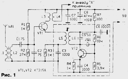
Schematic diagram of the Converter shown in Fig.1.

The signal of the radio, the adopted antenna WА1 and outlined L1 L2 SS with frequency 69,4 MHz, is fed to the mixer made the transistor VT1. The local oscillator is made transistor VT2. The generation frequency of oscillation stable quartz resonator ZQ1. Through coupling coil L5 voltage of the local oscillator is transmitted in the emitter circuit of the transistor VT1 mixer. The mixer loading coil is L3, on which stands out the signal with the sum frequency heterodyne input and signals. Through coupling coil L4 he enters the radio range 88...108 MHz or second (radiating) antenna.
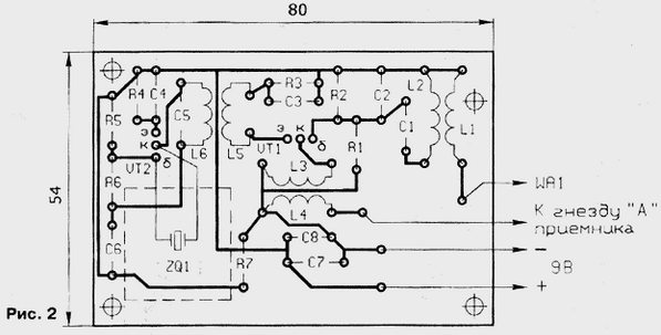
In Fig. 2 shows a printed charge Converter, made of foil fiberglass.

All the used type resistors MLT-0,125. Capacitors, except C8, tubular or disk. The capacitor C8 is any oxide. Transistors KT315 with any letter the index, they can be replaced by CT or KT361 (the latter change the polarity of the power source and capacitor C8). The capacitor C5 should have a capacity of 33 - 68 pF at a frequency of a quartz resonator within 7.5...of 9.5 MHz and 18 - 33 pF - for large values of the frequency. It capacity is established empirically by adjusting the device.
Coils L1 and L2 are wound wire sew-1 to 0.4 on the rod of ferrite brand N. Its length is 14, with a diameter of 2.8 mm., the Number of coils L1 - 4, L2 - 6. The coils L3 and L4 - frameless with an internal diameter of 5 mm, each has five turns of wire Sew-2 0,35. The coils L5 and L6 wound on a frame diameter of 7 mm with podstroechnik carbonyl iron filters from the if boards image or sound any television receivers. The number of coils L6 - 14, the winding turn to turn, in close proximity to the frame comprise a coil L5, having two turns. For winding wire used sew-2 0,35.
The Converter consumes less than 10 mA. The adapter should have a good filtration and stabilization of the output voltage.
The adjustment of the Converter start with checking the operation of the oscillator. Control his arousal easiest probe, whose scheme is shown in Fig. 3. It should be connected parallel to the coil L5. The connection is arbitrary. The measuring head RA1 fit any of the current total deviation from 50 to 200 the ICA. In the author's version of the probe was used without any alterations small dial gauge type M476 used in reel-to-reel and cassette recorders and tape recorders.

Adjustment of the generator is produced by rotation of podstroechnik coils L5, L6 until then, until the indicator needle of the probe not deflected to the maximum possible the magnitude. If the deviation is small, it is necessary to reduce the resistance resistor R1 (Fig. 3) to 7.5 ohms.
For steady excitation oscillator is recommended podstroechnik set in the average position of the zone in which it is retained generation. This zone is determined slow rotation of podstroechnik coils L5 and L6 from the beginning of generation till failure under the direction of the probe.
If the specified method is not able to achieve the mode of generation of the local oscillator, it is necessary to check the correct installation of this cascade, the serviceability of the elements and try to pick up the capacitance of the capacitor C5. It should be noted that there are quartz crystals, which are difficult to initiate at the third harmonic, even if they work well on the main. This quartz resonator must be replaced.
After that, the receiver with the Converter take one of the famous (for a given region) radio stations within the frequency interval of the scale 92...100 MHz and adjust the input oscillatory circuit by sliding or dragging of turns coil L2 to obtain good sound quality of the received program.
In some regions, where the television broadcasting with the use of the 4th and 5th of television channels, you may experience compatibility issues operation of the Converter and the TV (especially if applied for TV indoor antenna or its surrogate species). In this case, the Converter it is best to connect directly to the antenna input of the radio wire minimum length, and the Converter is placed in a metallic screen. If the signal is transmitted to the additional receiver antenna connected to the coil L4, it must have a minimum length (about 20 mm).
Author: D. Atayev, Sterlitamak, Bashkortostan


