


")

Many LW and УSW antenna, in particular television, belong to the class of symmetric antennas. When powered antennas via coaxial feeder, their work is largely dependent on the implementation of transitional balun. Often, however, hams, manufacturing the antenna, do not do such devices or design them correctly, based on the erroneous recommendations, which are found in some popular books on the antenna devices.
This article describes ways of balancing of antennas and properties of some balun, and recommendations for their implementation.
Immediate joining coaxial feeder to the symmetric antenna (e.g. dipole) breaks the symmetry of the currents in it and leads to the appearance of the current on the outer surface of the screen, feeder, that is, causes the antenna-feeder effect. In Fig. 1,a shows the connection of the dipole with the feeder. Thus the output voltage of the feeder is applied not only to the input terminals 1-2 dipole, but also to one clamp 2 and the shielding shell 3 of the feeder.
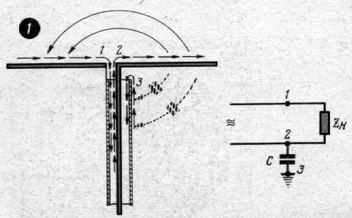
Fig. 1
The voltage between the terminals of the vibrator causes the symmetrical currents closing with one half of the vibrator to the other, as shown in Fig. 1,and the solid arrows. The tension between the right half of the vibrator and the sheath of the cable causes additional current, shown as dotted arrows. The emergence of this current leads to radiation (reception) feeder electromagnetic energy, which breaks the symmetry of the currents in the antenna and eventually distorts the radiation pattern.
In Fig. 1B shows the equivalent circuit of the symmetrical antenna is directly connected to a coaxial feeder, where the antenna is depicted in the form of the resistance RL of the load output terminals of the generator or user (transmitter or receiver). As can be seen from the diagram, one of these terminals will be connected not only with the load resistance RL, but also to ground via a capacitor, the plates of which are vibrator antenna and the shielding sheath of the feeder. Thus, the symmetry of the antenna is broken. Therefore, to connect the coaxial feeder antenna with symmetrical use special pods, also called balun, which achieve electrical symmetry of each half of the antenna relative to the shielding sheath of the feeder.
The transitional device type "locking the Cup shown in Fig. 2,and.
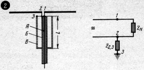
Fig. 2
In this arrangement, the input terminals 1-2 vibrator antenna directly connected to the inner and outer conductors of a coaxial cable, which is placed inside a metal Cup In on its axis so that the walls of the Cup and of the shielding shell B cable form a coaxial line with a characteristic impedance r (formula for calculation of the wave resistance coaxial and two-wire lines appear in the magazine "Radio" N 11, 1962). The input impedance of this line between points 2 and 3 is equal to:
When l=l/4 the value of Z2,3 is high, the current from point 2 to point 3 starts flowing, and the currents on both sides of the antenna will be equal. If the length l of the glass In a l/4, Z2,3 will not be large and, as can be seen from the equivalent circuit of Fig. 2,b, symmetry is broken: in point 2 of part supply will be branched off to the ground and the voltage between earth and 1-2 points will no longer be equal and opposite phase. Therefore, the bandwidth of such a balun device is small. Usually it does not exceed 10% of the value of the fundamental frequency to which the designed device.

Fig. 3
Frequency band balun device with a glass can be increased by the introduction of the second coaxial line segment with the same characteristic impedance as that of the glass (Fig. 3,a). Thus, as can be seen from the equivalent circuit (Fig. 3,b), resistance points 1 and 2 relative to the ground will be equal, regardless of their magnitude, that is, Z1,2=Z2,3. Due to this, the antenna power will be symmetrical in a wide band of frequencies. The difference between the devices is shown in Fig.3 and Fig.4, is that the last two elements (B and B') are placed next, forming a loop on the end of the two-wire line.
The input impedance of this balun device is equal to
where r'- impedance two-wire line.
Balun device of Fig.4 simply by design, operates in a wide band of frequencies and in the Amateur practice is used most often. One of the conductors of this balun device is the shielding sheath of the coaxial feeder (element B), as the second (element B') can be taken either end of the cable from which the feeder or tube of equal diameter. The main advantage of this device prior to (Fig.3) - halve the length.
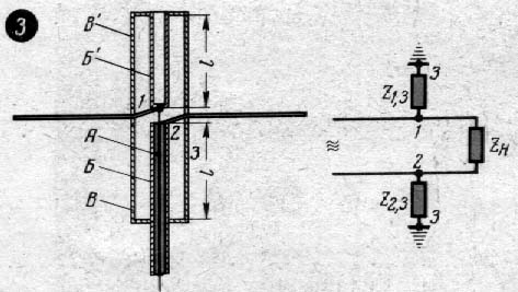
Fig. 4
In Fig.2,3 and 4: And - lived internal coaxial cable,
B and B'is the outer braid of the cable, B and B' is a metal cups.
Diagram of a balun device type "U-knee" shown in Fig.5,and. Here the Central wire core of the coaxial feeder is attached to the clamp 1 of the left half of the vibrator. From this point the voltage to the clamp 2 right half of the vibrator is fed through a section of cable of length l/2, where l is the wavelength in the cable (including shortening). Phase voltage with the passage of the part of the cable length l/2 is shifted by 180°, so the terminals of the vibrator is brought to the desired antiphase voltage. Shielding of cables interconnected.
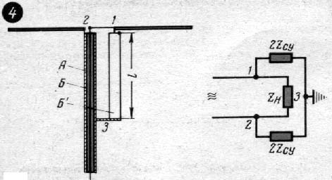
Fig. 5
Author: K. Kharchenko; Publication: www.cxem.net