When installing a surrogate and invisible antennas placed stationary, or temporarily operated indoors, usually difficult to adjust the resonance. Since these antennas typically are surrounded by conductive objects, their actual resonance frequency, compared with theoretically calculated, moves down, and they need to be setup directly at the installation site. Wire surrogate antennas are particularly susceptible as the detuning under the action of closely spaced conductive objects, and when approaching the person, causing them the resonant frequency changes significantly. As a result, these aerials installed secretly in the room, often do not perform satisfactorily. So if you install one type of surrogate antenna in different areas, there are difficulties with its setting.
To reduce the destabilizing impact of the above mentioned factors on the resonance frequency and the antenna to work, as a surrogate invisible antennas you can use a broadband single-ended vibrators. Were tested belt asymmetrical vertical antenna made of aluminum foil food. On one side of the foil was glued strips of 10 cm Antenna attached to a wall of a room by means of pins. As the earth uses the same band of foil length 5 meters, mounted on the baseboard of the room. The appearance of such antenna is shown in figure 1.
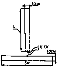
Fig.1
To operate the antenna in the 21 MHz band, the original length L was chosen to be 3.5 meters. In the study of the input impedance of the antenna using high-frequency bridge, it was found that this antenna has a resonance at a frequency of 19.2 MHz, while its input impedance was equal to 38 Ohms. The second resonance antenna was at a frequency of 26.4 MHz, at this frequency the input impedance of the antenna was equal to 350 Ohms. To configure the antenna on the 21 MHz band its top was rolled into a tube, as shown in figure 2. When the length L is equal to 3.1 m, resonance frequency of the antenna was equal to 21.1 MHz if input resistance of 39 Ohms, the second resonance frequency was equal to 28.1 MHz at the input antenna impedance 350 Ohms.
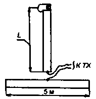
Fig.2
When placing the antenna in the room in various conditions - on the wall of the room, near conductive objects in free space, its resonant frequency is changed slightly. This shows that band antenna can be installed in different rooms with different surrounding the antenna setting. This requires minimal setup in resonance with respect to the environment. To feed the antenna range 21/28 MHz best through a two-wire line impedance equal 130-160 Ohms and an electrical length equal to l/4 in the range of 28 MHz. As this line is suitable mains cord with thin veins. The wave resistance of the cord is easily determined as follows. Cut the cord length of at least 1 meter, open at one end, is connected to the RLC-meter, and measure the capacitance lived relative to each other. Then the cores at the end of the cable short-circuit, and measure the resulting inductance of the line. Knowing the capacitance and inductance are impedance surrogate transmission line from the known formulas:
Z=Sqr(L/C)
where Z is the wave impedance (Ohms), L is the line inductance (Henry), C - line capacitance (farads). This method allows to determine the wave resistance of the line is sufficient for Amateur radio practice accuracy. Obtained a very good agreement of the antenna when it is working on the bands 21 and 28 MHz, and besides, the antenna can be connected to the transceiver with the output stage on 50-75 Ohms without any matching device.
Configuring tape the antenna to resonance by its location in specific conditions, easy to carry out by collapsing the leaf antenna. When reducing the length of the antenna to 1.9 meters to get the first resonance in the range of 28 MHz if input resistance of 36 Ohms. This gives you the opportunity to feed the antenna via a coaxial cable with a characteristic impedance of 50 Ohms, and if you change the range to quickly configure the antenna operating range by changing its length. As shown, a more rational use to work on the band 28 MHz antenna length of 3.1 meters. In this case, the strength of the received signals during the transition from band antenna with a length of 1.9 m to tape the antenna length 3,1 m power signals has increased by 1 to 1.5 points.
The collapse of the band of the antenna can be set to a higher resonant frequency. If necessary, adjust the antenna at a wavelength lower than the resonance frequency of the antenna it is possible to make the cutout portions of the foil so that the leaf antenna was a form of inductors, as shown in figure 3.
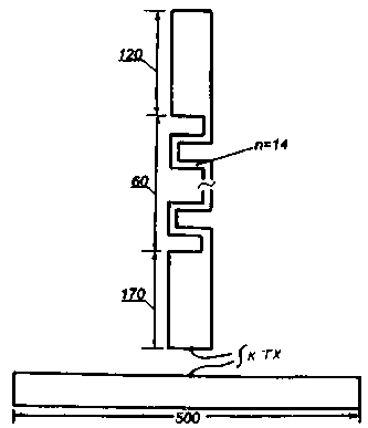
Fig.3
In my case, the antenna shown in this figure, had a resonant frequency of 18.1 MHz. Its input impedance was equal to 38 Ohms, which almost approaches the theoretical input impedance of asymmetric vertical quarter-wave antenna. The number of lanes of the coil n is the length of 60 cm was equal to 14. The second resonant frequency of the antenna is obtained of 25.2 MHz with input resistance of 350 Ohms. This antenna works well on the bands 18 and 25 MHz. For its power on both bands is advisable to apply two-wire line length equal to l/4 in the range of 25 MHz and a characteristic impedance of 130-160 Ω, as was done above.
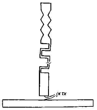
Fig.4
The width of the resonance line of antennas shown in figures 1-3, when changing the input impedance of the antenna by an amount equal to the square root of 2, was not less than 1.2 MHz on those bands where the antenna had a low input impedance, and at least 1 MHz band where the antenna has a high input impedance.
For more exact tuning of the antenna in the upper end of the range of her work can make notches in its upper canvas because of "saw". In this case, its resonance frequency can be easily translated into the desired frequency range. Bandwidth of the antenna is slightly less. Start to produce a sawtooth appropriate cutouts to the top of the antenna. In the lower part (below the coil or below half the length of the antenna) cutouts should not do it.
When the location of the transceiver away from band antenna, antenna power, it is advisable to produce according to figure 5. In this case, it is powered via a symmetrical two-wire transmission line characteristic impedance of 140-160 Ohms. Line length equal to a quarter wavelength at the upper range of the antenna (that is, its input impedance is high). After a two-wire line is connected coaxial cable with a characteristic impedance of 50 Ohms and an electrical length more about 20-30% of the half of the resonance wavelength of the antenna at the lower range.
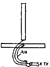
Fig.5
Vibrator band antenna can be positioned not only in the middle "ground" ribbon, but with one of its edges. It is desirable that the distance from the vibrator to the edge of the "ground" of the tape was not less than 1.5 meters. Such a construction of the antenna is beneficial in that case, if the room are conductive objects, and the antenna should be placed as far away from them. or to remove it from the transceiver or from the equipment, which when transferred bleed. If it is desirable to produce a directional radiation band of the antenna, the antenna system can be performed according to figure 6.
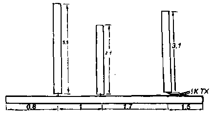
Fig.6
Passive reflectors for the corresponding ranges 21 and 28 MHz are made of the same foil for the vibrator, and placed on the wall of the room. It should be noted that, such a construction tape directory antenna is not optimal and provides weak directivity of the antenna. To increase the directivity can be tunable band Directors by coagulation or cutting out coils in them or saw. But any change to the antenna situation will make the detuning in passive elements and impact on the operation of the antenna. Figure 7 shows a simplified implementation of directional band antenna suitable for antennas on 21/28 MHz and 18/25 MHz. In this case, the length of earthen foil is slightly more than 5 meters.
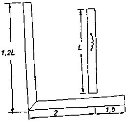
Fig.7
Experiments with band antennas have shown that it is possible to perform surrogate invisible antenna operating in two simple Amateur bands, the antenna can be placed stationary in an inconspicuous execution on the wall of the room, behind the cupboard, curtain. When working in campaigns, in the country, the hotel can be carried in a collapsed form without attracting attention, and then be placed in a convenient place. Since the antenna is made in an unprotected from the weather, she will not long be operated outdoors.
Author: Grigorov, I. N., RK3ZK; Publication: N. Bolshakov, rf.atnn.ru


