


")

Independent production of the antenna is not an easy task for Amateurs. Often the authors of the various antennas are not paying attention to the description of technology the manufacture of antennas, and it is very important for those who will try to repeat them. Not knowing of manufacturing technology, it is difficult to fully assess their own opportunities. Their revaluation often leads to good design, despite already expended materials, and remain unfinished. In the article describes in detail the construction of the antenna in the range of 20 meters. Some manufacturing techniques can help in the manufacture of other antennas the ranges.
The problem of choosing the antenna was before the staff of INTA radio club (RK9XXS) at the very beginning of its activities. Even then, it was resolved: to do only serious antenna. Knowing well that the antenna quickly does not, decided to start to collect materials, and already the basis of their number, to decide which antenna build. During the month managed to find 10 duralumin plate for the high jump length of 3.6 m, 10 segments 30 mm tube length 1.5 m, two pipes medical stretcher with a diameter of 36 mm, two six-meter duralumin pipe with a diameter of 60 and 70 mm and one three-meter pipe of 60 mm diameter. This material it was enough for the construction of a 5-element YAGI antenna.
Having the experience of designing antenna systems using a computer and manufacturing designed antennas, began preliminary design of the antenna. The first estimations showed that it is most advantageous to build the antenna on an extended traverse: the higher the gain, the better the ratio of front/rear. The main requirement for the antenna club, in our opinion, is the ability to minimum SWR to work in the frequency range 14…14,35 MHz. This is due to just, varied interests of the members of the club: one loves Telegraph station, other SSTV, and the third a fan of island expeditions, fourth - loves MT-63.
When was subsequently modeled antenna with a maximum gain in the direction of the main lobe, it turned out that our antenna loses all 0,5…0,7 dB. It was OK for us. Calculations conducted by the program YAGIOPTIMIZER, and checked the program NEC4WIN95. In fairness, it should note that both programs are very similar in the end result, though there were some discrepancies.
The dimensions of the antenna elements: reflector - 10.7 m, vibrator - 10.3 m; Director 1 - for 9.88 m, Director 2 - 9,58 m; Director 3 - 8,9 m antenna Features: the gain is 11.6 dB; the ratio of front/rear - 24 dB; the ratio of front/side - 35 dB, input impedance is 50 Ohms.
So the main dimensions were determined, it's time for technological solutions.
Manufacturing technology antenna was chosen so as to minimize the amount of "paid" work and the bulk of the details could be run independently from the help of simple tools. For works needed a drill, scissors metal, hacksaw, hammers, pliers, taps, dies, wrenches wrenches, screwdrivers and other small items. Welding only six simple of nodes. Turning - 10 dural sleeves. Everything else is made on their own, without the use of special equipment.
Most simply resolved the issue with traverse: in the middle of the pipe arranged with a diameter of 70 mm, with the two sides to put her pipe with a diameter of 60 mm, the Gap between pipes eliminated strip steel strip with a thickness of 1.5 mm, tightly wrapping it thin pipes. The place of the joint recorded from turning bolts M 10x80. On the distance of 1500 mm from the ends drilled two holes and bolted them M 10x100 two steel hinges dimensions 30x120x5 mm for fastening the upper and side stretch (Fig. 1).
On marked places set plate elements (Fig. 2). These site completely isolate the elements from the beam with a minimum capacity between them. Plate elements are made from a steel plate having a thickness of 3 mm and textolite plate dimensions 100x250x15 mm In steel and textolite the plates are drilled 16 coaxial holes of 6 mm in diameter, then in steel plate eight holes reamed to a diameter of 25 mm, It is necessary for ensure that the ladder fixing the elements did not have contact with steel a plate. Then a steel plate drilled four holes with a diameter of 8 mm for fastening the pad to the traverse and welded tubes with a diameter of 17 mm and length 500 mm for the upper stretch of the item (hour). Plate bonded between a not through reamed holes eight bolts MH.
Ladders made of steel geotagging rod with a diameter of 8 mm For mounting the ladders were made of 6 mm in diameter (used building nails). First, you need to cut the rod to the desired length, then ends threaded on a length of 30 mm, and then to bend the ladder on the anvil to the desired shape. To calculate the length of the rod is easy by the formula
L = 1,57*(D+D) + D + 2*M + 40,
where L is the required length of the rod; D - diameter of pipe that attaches the ladder; d -the diameter of the rod is made of a stepladder; M is the thickness of the parts to which is fixed a pipe; 40 mm - stock for the fastening nuts.
A simple way of bending the ladder shown in Fig. 3. In the process of bending one the hammer is being instructed on the ladder the second apply strong blows. Profile the ladder is controlled by a template or fasten the pipe.
The antenna elements (Fig. 4) made from a piece of pipe with a diameter of 36 mm (in center), two straps for the high jump and two pieces of 30-millimeter tube (at the ends). Strap for jumping tightly inserted into the pipe with a diameter of 36 mm and fixed standard clamps and pieces of tubing are joined with strap specially machined bushings aluminum and aluminum rivets wire with a diameter of 5 mm At the intersection of set a loop for attaching the upper and external stretch elements. The loop is made of a rod with a diameter and a length of 6 90 mm (you can use long nails). One end of a length of 20 mm threaded MH, the second end is bent into a ring mandrel with a diameter of 15 mm.
The node of the yoke (Fig. 5) takes up most of the load static and dynamic in nature and must ensure high durability. It is a steel plate thickness of 4 mm plate Size is determined by the length of the beam and the weight of the antenna, the minimum size of "b" to this antenna - 500 mm In the plate drilled holes for mounting clamps beam clamp mounting plate to the mast.
The hole pattern is as follows. The distance "A" should be equal to the sum of the diameters of the mast and u that secure the plate to the mast. In our if the diameter of the mast is 52 mm, and the ladder is made of a rod with a diameter of 8 mm, so the distance between the centers of the holes is 60 mm, the Distance "B" should to be equal to the sum of the diameters of the yoke and u-attaching the yoke to the plate. In our case, the beam diameter is 70 mm, and the diameter of the rod from which made ladders, is 8 mm., the Distance between the centers of the holes is 78 mm.
The number of ladders the yoke for such a heavy antenna at least 6. It determines the reliability of the yoke. The number of ladders mounting plate to the mast for long antennas should be 6-8. It determines the strength retention beam on the mast. We chose six of the ladders.
After marking and drilling of these holes in the bottom corner of the hole made for bracket side stretch marks. The diameter of the hole should be equal to the diameter the pipe selected for the bracket. Pipe bracket is selected with a diameter of 1.5 inches, i.e. 37 mm Length pipe bracket (size "D"), we chose To 1000 mm. the pipe bracket at the ends drilled two holes with a diameter of 12 mm, will be inserted tensioning bolts side stretch marks.
Pipe bracket is inserted into the hole in the steel plate so that the length the ends are the same. After that, the pipe must be carefully scald arc welding from both sides. The mount is carefully sanded and painted with oil paint for exterior use.
The tensioning bolts top and side stretch is made from a steel rod with a diameter of 12 mm and have a length of 250 mm. One end of the rod is bent into a ring on the mandrel with a diameter of 15 mm from the other end for the rest of the length of the threaded M12x1,5.
Lateral and top marks traverses to produce the best in the Assembly process antenna, because their length is determined by the center of gravity of the antenna system. Fastening stretch traverses shown in Fig. 6.
The antenna Assembly. First, assemble the yoke of the antenna, as described above. The yoke is placed on a clean, flat, horizontal surface size 12x16 M. On the yoke with u-set plate elements, and them (also using stepladders) is collected by the antenna elements. It should pay attention to the alignment of all elements of the antenna.
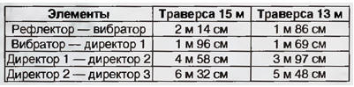
The distance between the elements shown in the table.
When installing the elements of the upper loop fasteners and external needs of stretch marks to be on top. Look at the antenna on top is shown in Fig. 7.
(click to enlarge)
Then produce a layout of the upper stretch of the elements and install them isolators. More than insulators will be installed, the less the parameters of the antenna will have top marks. In the case of dielectric (nylon, hemp) upper stretch insulators can not install. Stretch marks are fixed at one end for loop on the elements, and the other for supporting arms, missing posters in drilled the hole racks (Fig. 8).
(click to enlarge)
For all of the attachment of stretch marks must be applied thimbles. External streamers attached to the loops on the elements. These stretch marks in places of fastening it is advisable to wrap the strips of galvanized sheet, then they will last a long time. External marks should be strongly but evenly tensioned. The most important thing is to ensure the correct position of the antenna elements. In our the design used steel cables to the top of the stretch marks and hemp the cord for the external marks.
After fixing all marks set matching device (Fig. 9). It is fastened by means of clamps or stepladders. The power cable is connected, fixed and navigate to the center of the mast immediately. The matching device body needs to protect the capacitors from rain and snow.
(click to enlarge)
Now the antenna is assembled and can determine its center of gravity. For this lift the yoke between the first and second Directors and by moving the point support, find the equilibrium position of the antenna. In this place the center host the yoke so that the bracket side stretch was at the bottom. Fastening the yoke to the mast shown in Fig. 10.
(click to enlarge)
Then measure the distance between the holes of the bracket and steel loops on the traverse. These sizes are made lateral stretching, making stock for tension.
Before raising the antenna, be sure to check all fasteners, tighten all the the nuts. Supporting the yoke in two places, raise the assembled antenna on the machine The UNZHA. which is fixed a gear with carrier pipe. Align the mounting unit to carrier pipe, fix it using stepladders.
Aligning the beam with the help of supports, measure the distance between the top of the the carrier pipe and the hinges that attach the top of the stretch marks. For these sizes make and install the upper stretch marks. Immediately need to ensure the tension of the upper and lateral stretch of the bar, the lack of controlling vertical and lateral deflection. This is the only Assembly work at a height of 3 m. Now the antenna is fully assembled and lifted the section on high, when where else can you work with a matching unit, carry out the adjustment omega-Aligner.
Setting. Two built in computer calculations of the antenna required only the settings of the matching device. Any lengthening or shortening of the elements and their movements on the traverse in the setting process is not performed. Setting matching device is to install engines capacitors in position, corresponding to the maximum power output with minimum SWR in the middle range.
In the case of establishing a matching device at a height of 3…4 m from the ground the setting is produced at a frequency 14100 kHz, it is necessary to check the SWR on frequencies of 14 and 14,35 MHz, where it should not exceed 1.1. I tuned the antenna The CWS should be no more than 1.1 in the range of 20 meters.
In the design and construction of the antenna participated Y. Pogrebin (UA9XEX), A. Kishen (UA9XJK), A. Kolpakov (UA9XKT), Bogomolov (UA9XBL), M. Grebak (UA9XEQ). General designer and superintendent of construction of the N. Filenko (UA9XBI).
Author: N. Filenko (UA9XBI)