There are two main problems that cause interest radio Amateurs, Amateurs and Amateur CB communications to the radio search and direction finding radio stations.
One of them is static. There are enough of them on the Amateur bands, and on CBS. This interference from industrial and domestic installations, and interference from out-of-band radiation of other services, and interference from radio stations that "quietly" use our ranges. To be honest, there are conscious interference from those to whom applies the concept of "radiohooligans". To eliminate this interference, it is necessary to determine the location of their source and origin, and then already to solve the problem with the involvement of, in particular, bodies of GSN.
The second problem is more of an everyday nature. After all, Amateur radio is not stands outside the interests of the family, and many Amateurs are happy to use your knowledge as a hobby and to address some of the household chores. It comes the radio search - locating beacon associated with some object. It may be your companion in the journey of mushrooms, and escaped from the owner favorite dog, and left in the woods in a clearing vehicle. This list can extend to infinity.
To publish the article, the author illustrates the radio search and direction finding on the example the use of CB radios, but constructive solutions that are it were of a General nature for equipment operating on frequencies below 30 MHz. This technique is not new. For decades it has been applied in sports direction-finding (the so-called "Fox Hunting").
The principle of operation of the direction finder based on the fact that in a free uniform space radio waves propagate in straight lines. Determining the point from which comes to an RF signal, can be set and the direction [1]. Note that the accuracy of direction finding strongly influenced, in particular, the reflection of radio waves from buildings, power lines, metal supports, etc.
Readers are provided with simple to manufacture antenna option, designed for use with a conventional portable CB radio and turns its receiver in the finder.
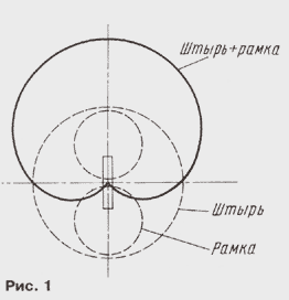
If taken vertically polarized wave antenna vertical polarization responsive to an electric field component (for example, a pin), the signal level will be the same when receiving from all sides (Fig. 1), i.e. the the radiation pattern of this antenna will be circular. It is clear that to determine the direction to the source of the signal in this case will not succeed.

If the reception of this wave on an antenna responsive to a magnetic component fields, such as round wire (frame), the received signal is will depend on its orientation. If the plane of the frame perpendicular to the direction of wave propagation, EDS minimum, and ideally equal to zero. When the rotation of the frame about a vertical axis EMF reaches the maximum value, when the plane of the frame is parallel to the direction of the transmitter. Chart orientation of the frame has the form "g" (Fig. 1).
This antenna is already possible to determine the direction, and finding the produce not peak, so as to determine its very difficult due to the smoothness charts, at least. Frame antenna allows to provide the highest accuracy in azimuth direction finding. However, due to the fact that it has two minima in the radiation pattern, to unambiguously determine the direction of the radio cannot.
To eliminate the ambiguity of the bearing, use the antenna representing a combination of two antennas - frame and pin. If the signals of these antennas properly phased and aligned in amplitude, after summing them the resulting radiation pattern will be with one maxima and one the low - cardioid (Fig. 1). Direction finding with it is carried out in the following okay. First, use a joint inclusion framework and pin, ie cardioid pattern, and to determine at least approximately in the direction the signal source. Then use one frame clarify this direction.
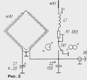
This combination is used to describe the directional antenna. It consists of frame, pin elements and their coordination. Its circuitry shown in Fig. 2. To switch the chart serves as a toggle switch SA1.

Frame is represented by an inductor in the form of a single turn of wire. For make the loop antenna is insensitive to electric component of the field, the wire frame are screened, while in the Central part screen made the cut. Using capacitors C1 and C2 set up on frame the average frequency of the operating range and agree to the entrance of the radio station (50 Ohms). Lengthening the coil L1 is used to compensate the capacitive component the input impedance of the pin, and a resistor R1 for the phasing of signals and alignment of the amplitude.
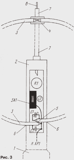
Antenna (Fig. 3) is made on the basis of staff from the radio station "Ural-R": used high-frequency connector 1 (bayonet), plastic pin holder 2, the casing and the inductor L1 (15...20 turns of wire sew-2 0.1 per frame with podstroechnik carbonyl iron diameter W mm). Plastic the holder 2 has a cavity which has the capacitors, coil inductance, a toggle switch and a trimmer.

Frame 3 is made from a piece of semi-rigid (as copper outer shell tube) cable impedance of 50 Ohms, with a diameter of 3 mm and a length of 65...70 cm Cable cut exactly in half, the center conductor on one side of each piece freed from the screen by about 10 mm and 5 mm. Then solder the Central conductors of a length of 10 mm to each other overlap the entire length. Place soldering envelop epoxy glue and put the plastic tube 4 suitable diameter and length of about 20 mm and also fill it with glue. After polymerization of the glue, but not earlier than a day, the cable is bent round on the subject of suitable diameter and solder the 5 screens on the length of 3...5 mm.
In plastic holder pin saw through the slots 6 to install the frame and drill the holes for the placement of the coil and resistor. Pin make collapsible, two parts, the first (7) - from the tube or rod with a length of 19...20 cm, and the second (8) - steel or other elastic wire length of about 30 cm pin Connection with holder and between the threaded parts. The first part of the pin and box mounted on the holder, thread fasten them to each other on a plastic the tube with the help of thread and fill this place with epoxy glue. They pour the installation location of the frame in the holder. After polymerization of the adhesive in the cavity of the holder temporarily place the rest of the details. Connections must be of a minimum length.
Then spend preset pin and frame. Pin through the coil connected to the input of the radio station and the podstroechnik coil L1 tune the maximum of the received signal. Then connect the frame and carry out similar tuning capacitor C1. If the capacitor and podstroechnik are about the middle position, all the details can be set continuously, securing them with glue.
In conclusion, total spend to set up and test pattern the antennas. This would require a low-power transmitter (to make it easier to determine the minima at the hearing), working on a long vertical antenna. The setting must be carried out in an open area, away from all sorts of buildings and items that can emit radio waves.
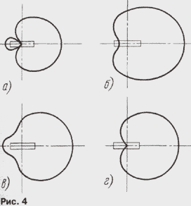
First, set up the frame (SA1 - in the "eight") to the maximum signal, and check her chart, she should be symmetrical and have a clear lows. Then agree on the pin: the engine of the resistor R1 is set to the middle position, the switch SA1 is in position "cardioid". The antenna directs the alleged minimum (the plane of the frame) on the transmitter and move podstroechnik coil L1, achieve minimum signal level. If the level is increasing or not changes, it is necessary to rotate the frame 180". The coil provides the phasing and resistor - amplitude adjustment. Resistor R1 sets the amplitude for obtain a cardioid.
Assistance setting up can provide Fig. 4, which shows the chart orientation at different ratios of signal pins and the frame. In Fig. 4,and see the diagram for the case, if the signal frame exceeds the signal pin; Fig. 4,6 - if the signal pin signal exceeds the frame; Fig. 4,with poor phasing, in Fig. 4,Mr. at the optimum matching. After adjustment details close the casing.

In a short article it is impossible to give all the recommendations on methods of direction finding. It can help the experience and special publications in [2, 3].
Literature
Author: Igor Nechaev (UA3VWIA)


