

From the editors. We asked well-known to our readers specialist antennas, candidate of technical Sciences K. P. Kharchenko to Express their opinion on the antenna, T. Gasparyan. In the article published below K. P. Kharchenko describes the different types of antennas operating over a wide wavelength range. In particular, it indicates that the antenna is proposed T. Gasparyan, is a form of inhomogeneous planar dipole type, and the proper design leads her (in his post so Gasparyan made mistakes, speaking of the dimensions of the antenna, the range working with will, and wrongly stated that it does not require balancing and alignment).
The problem of creating band antenna relatively simple design is an old one. Partly its practical resolution she had received in 1937, thanks to the efforts of S. I. Nadenenko. The proposed design of the symmetric band of the vibrator, shown schematically in Fig. 1, has stood the test of time and is widely used so far.

Fig.1
In the study of symmetric directional characteristics of the vibrator, it was found that when the lengths of the arms of the vibrator lying in the range from zero to 0.65 l, (where l is the wavelength), the direction of the main radiation perpendicular to the axis of the vibrator.
Consequently, the requirement of invariance of the direction of the main radiation applicable to the band antennas is performed for a dipole in a very wide wavelength range. The input impedance of dipole depends on the ratio L/l and the magnitude of the wave impedance z a vibrator. The latter dependence separately for active (Rin) and reactive (Hvh) components shown in Fig. 2,a and 2,b. It could be seen that with decreasing z a fluctuation bits and Hwh be less. Reduce wave resistance achieved by increasing the diameter D of the vibrator.
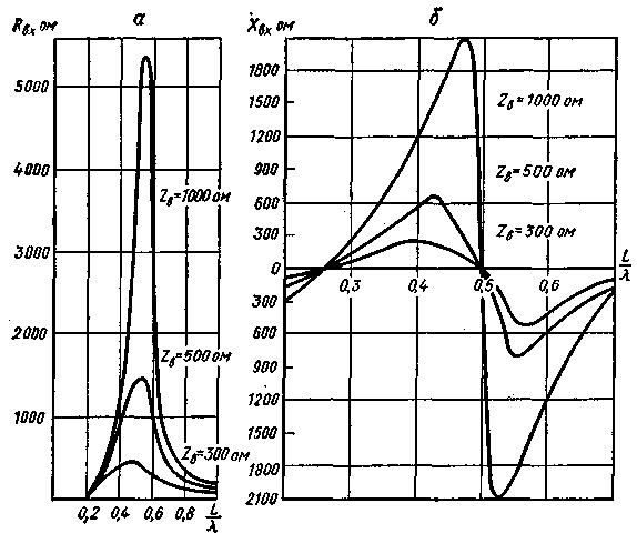
Fig.2
To reduce wind loads and the weight of his shoulders vibrator made of individual wires placed along the generatrices of a cylinder. When six to eight wires characteristic impedance of such a vibrator is approaching the characteristic impedance of the vibrator, the shoulders of which is made of a cylinder with a solid surface.
For better coordination in the wavelength range of the input impedance of the antenna with a characteristic impedance of the feeder must be properly selected. The mode of operation of the feeder is entirely determined by the ratio of the traveling wave, which depends on the ratio between z a and Zф where Zф, - characteristic impedance of the feeder. In Fig.3 shows curves showing how To change depending on various L/L, z a and Zф. If z a=300 ohms and Zф=200 ohms (curve 1) in the entire wavelength range mode feeder can be considered satisfactory, when z a=1000 ohms and Zф=600 ohms (curve 3) the feeder will operate with very low efficiency Thus, for normal operation of the feeder, it is necessary that in the beginning of the range when the bits are small (see Fig.2), and in the middle of it, when bits maximum, the value Zф not too far either higher or lower side of the values of Rin.
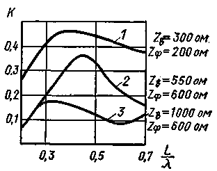
Fig.3
In the calculation of the symmetric band of vibrators to work at short wavelengths chosen limits and the values of the parameters of the vibrator and feeder according to the following formulas:
4L>l>1,56 p;
D=0,03 lмакс;
Zф=200 ohms.
At wavelengths longer than 4L violates the condition of matching of the antenna with feeder, and the shorter waves of 1.56 L - forks chart of the radiation in the main direction.
As a band antennas are used and the so-called shunt vibrators, designed by G. 3. By Eisenberg.
Schematically shunt vibrator shown in Fig. 4. The active component of the input impedance of such a vibrator with dimensions given in Fig. 4, is changed
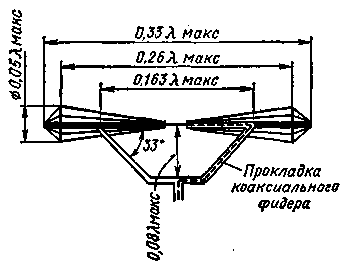
Fig.4
in the frequency range from 90 to 340 ohms. If you replace the shunt vibrator is equivalent to the two-wire line, it will have a circuit shown in Fig. 5. As can be seen from it, in an equivalent circuit is open at the end of line 1-5 - 2-6, consisting of two parts 1-3 and 2-4 and 3-5-4-6 with different wave resistance and the shunt 3 - 7-4. Between the shunt and the plot line 1-3-2-4 there is considerable distributed electromagnetic coupling, is not reflected in the equivalent circuit.
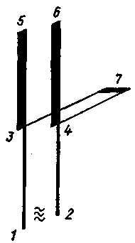
Fig.5
The presence of the vibrator two branches (open and closed) creates favorable conditions for the input resistance changed as little as possible. This allows selecting the dimensions of the vibrator, to achieve good matching its input resistance and wave resistance of the feeder in a wide range of frequencies. The presence of the shunt leads to the transformation of the input impedance in the direction of its increase. This circumstance can be considered an advantage when there is a need to gain common-mode lattice of shunt vibrators and use a symmetrical high impedance feeders. When powered antenna coaxial feeder with a relatively lower impedance, on the contrary, it is a disadvantage.
Based on the study of the properties of inhomogeneous long line losses the author of these lines showed the possibility of constructing a frequency of the vibrator with relatively smaller than those previously described, windage and weight. The overall look of this vibrator is given in Fig. 6, and its equivalent circuit, in the form of an inhomogeneous two-wire line in Fig. 7. Here the plot inhomogeneous line with Z b can be regarded as a kind of transformer losses (this is useful Losses due to radiation of energy), transforming bits and Hwh towards improved matching with the low-impedance feeders.

Fig.6
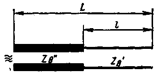
Fig.7
Said figure illustrates.8, curve 1 which shows the dependence of Rin from L/l to homogeneous vibrator (the diameter of the shoulder is the same throughout its length), and curve 2 - heterogeneous vibrator (the diameter of the shoulder along its length varies). The values of parameters (see Fig.1 and Fig.6) and L for both vibrators were taken the same, and for inhomogeneous vibrator, in addition, l/L=0,47; D/D=9.
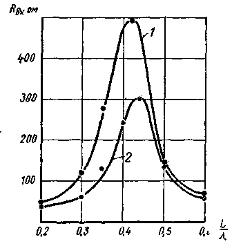
Fig.8
Curves of Fig. 8 show that the equivalent impedance of heterogeneous antenna compared with a homogeneous 1.3-1.4 times (for the given ratios). At the same time in the manufacture of heterogeneous antenna projected to be about twice her weight and windage compared with the above-described vibrator both bulk and planar types, owing to the considerable reduction in the transverse dimensions of their end sections.
A slightly modified variant inhomogeneous dipole planar type proposed radio Batumi And Gasparyan, shown in Fig. 9.
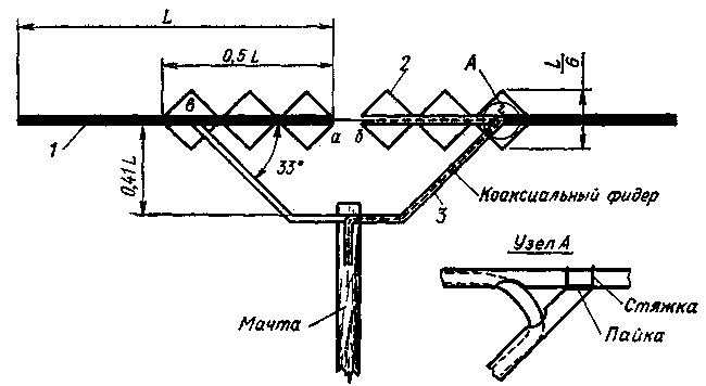
Fig.9
The vibrator consists of two tubes 1 and length L=0,22-0,24 where lмако lмакс - maximum wavelength operating range. The diameter of the tubes is selected so that the vibrator was mechanically durable. They mounted a wire or tubular structure 2, which should have between their elements and tubes 1 galvanic contact. This structure performs the role of a matching transformer. For strip feeder and mounting of the vibrator on the mast is used, the shunt 3 (from the tubes), which at points b, g also has a tube 1 galvanic a contact. Cable (feeder) may be routed either through the tubes of the shunt from the top (tied to them), or within them, as shown in Fig. 9 by the dotted line At the point b to the tube 1 solder the braid of the cable, and in the point a and its center conductor. For installation of the vibrator can be applied to the mast of any material.
Literature
Author: PhD. tech. Sciences K. Kharchenko; Publication: N. Bolshakov, rf.atnn.ru


