


")

To offer readers the paper the description and calculation of the frequency-independent antenna. So far this class of antennas did not find application in Amateur practice. At the same time, the use of such antennas are very attractive, because it allows you to do one antenna system when working on multiple ranges (for example, 14; 21 and 28 MHz on LW or 144 and 430 MHz УSW).
Compared with common antenna "wave channel" described system has a smaller size in the horizontal plane. Perhaps the only drawback is the need for the implementation of elements in the form of frames with sides of 0.5 l for the 14 MHz band is a structure of considerable dimensions. But such is antenna technology. The eternal dilemma - either large size or low efficiency. This question every fan decides based on their specific conditions. As for effectiveness, the frequency independent antenna, apparently, has the advantage as before "wave channel" and different "squares".
The described antenna developed at the initiative of shortwave, which is well known in our country and abroad, selfless radio sport enthusiast, a former member of the Presidium of the fed of the USSR Igor Nikolaevich Zhuchenko (UA1CC).
Published below the article the authors and the editors dedicate to the memory of I. N. Zhuchenko.
Typically, antennas, which use only, narrowband and have a relatively low gain. Therefore, the overlap of the Amateur bands 14; 21 and 28 MHz is typically accomplished by making three antennas, and the provision of long-distance communication - increasing transmitter power or complexity of antenna systems. At the same time, the task of providing long-distance communication can be successfully solved without umashree transmitter if you use narrow-beam frequency-independent antenna with high gain.
Various authors proposed a number of design decisions to create a frequency-independent (automatic process) antennas, which have a gain of 9 to 12 compared to an isotropic radiator. The following is a description of a broadband antenna automatic process, the increase in radiation efficiency which is achieved through the use of resonant elements, in the form of dual frames.
Antenna, a General view of which is shown in Fig. 1, consists of rigidly performed two-wire power line and along parallel to each other radiating elements. The dimensions of the radiating elements and the distance between them varies exponentially with the proportionality factor t. The elements are excited in such a way that the radiated elements of the active region energy-phase is formed in the far zone (below the active region should be understood as the group of vibrators, the geometrical dimensions of which are close to the length of the resonant element 0,25 l).
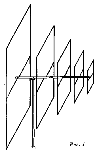
Fig.1
Radiating element has the shape of a square whose side is equal to 0,5 l, (Fig. 2). Quarter-wave jumper form two symmetrical loop powered two-wire line at points a - a'. The direction of the main currents that form the pattern indicated by the solid arrows. The electromagnetic field formed by the currents indicated dotted arrow, cancel each other out. Thus, the resonant element represents a three-phase grid.
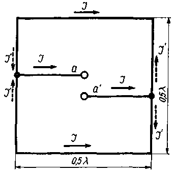
Fig.2
In Fig. 3 shows a drawing of the antenna in the horizontal plane. From this it follows that the calculation of the antenna is reduced to the solution of a right triangle. Note: the principle of operation of the antenna is not broken, provided a reasonable reduction of its longitudinal dimension, which has crucial when building antennas shortwave range.
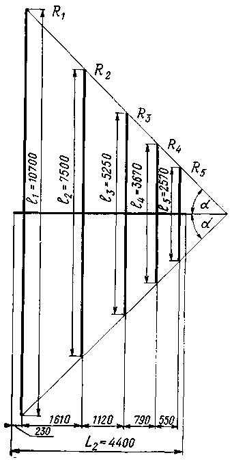
Fig.3
The dimensions of the shortened antenna are determined frequency range. So, for overlapping frequency range 14; 21 and 28 MHz necessary and sufficient condition is the presence of resonant elements corresponding to the boundary frequencies. However, in this case the directional properties of the antenna at the frequency of 28 MHz will be slightly lower than a frequency of 14 MHz, so that the active region on the upper frequency is limited to one element. Therefore, the shortening of the antenna is preferably made so that the upper frequency worked at least two of the resonant element.
The calculation of the antenna
Based on the conditions of providing reliable communication with correspondents, expect (or ask) the required antenna gain G:
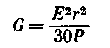
where: E - field strength (sensitivity threshold of the receiver), mV/m;
P is the transmitter power, W; r is the distance, km.
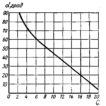
Fig.4
From the graph Fig. 4, we define the angular size of a.
From the graph Fig. 5 we find the longitudinal size L (Lo, L1 or L1 depending on the degree of shortening, where:
Lo - full length antenna, L1 is the minimum possible
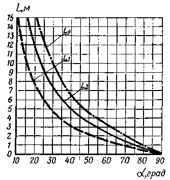
Fig.5
the length of the shortened antenna, L2 is the length of the shortened antenna with the increase of the active zone on the upper frequencies).
From the graph Fig. 6 determine the value of constant of proportionality so Here Gопт corresponds to the optimal gain and the Gопт-D and Gопт-2D-decrease gain on 1 and 2 units.
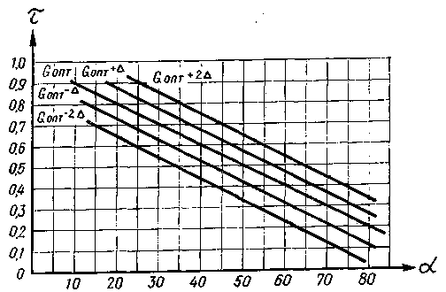
Fig.6
From the graph Fig. 7 determine the number of n radiating elements.
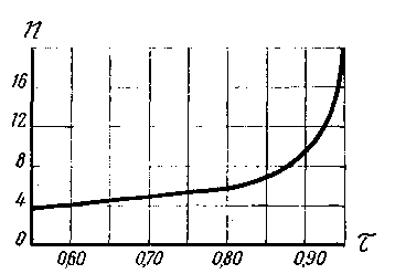
Fig.7
Calculated resonant length of the radiating elements:
l1=0,25 lмакс
l2=tl1
. . . . .
ln=tln-1
The designated location (distance to the first element) emitting elements of R along a two-wire line:
R1=L
R2=tR1
. . . . .
R2=tRn-1
In the manufacture supply two-wire line, the estimated size L should be increased by the amount of 0.13 lмакс to obtain good matching and eliminating the reverse radiation: 0,03 lмакс - before resonant element corresponding to the upper cutoff frequency, and 0.1 lмакс - after resonant element corresponding to the lower cutoff frequency.
To guide the selection of the antenna in the frequency range 14-28 MHz in the table gives a comparative assessment of its geometrical and electrical parameters.
Table 1
G
a, deg
Lo, m
L1, m
L2, m
t
n
18
10
30
15
18,5
0,9
8
15
20
15,3
7,5
10,5
0,8
4
12,5
30
9,3
4,7
7,1
0,7
3
10
40
6,4
3,2
5,0
0,6
2
9,5
45
5,35
2,6
4,4
0,7
5
8
50
4,5
2,1
3,5
0,5
2
6
60
3,1
1,4
2,5
0,4
2
4,5
70
1,95
0,9
1,5
0,3
2
3
80
1,0
0,5
0,7
0,2
2
The dimensions corresponding to G=9,5, shown in Fig. 3. As L is adopted, the size of L2. The antenna shown in Fig. 8.
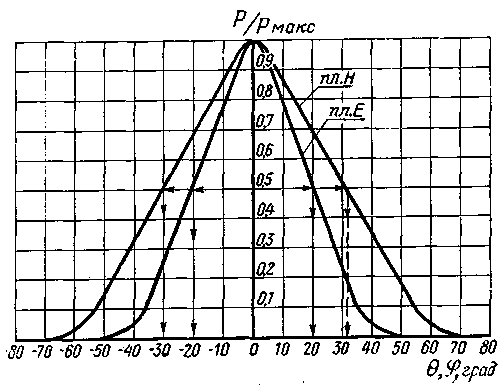
Fig.8
Antenna design
Antenna and two-wire power supply line can be made of steel or dural tubes. The constancy of the wave resistance of a two-wire line is provided by means of insulators made of a high-frequency dielectric material or a dry, well-oiled wood. Characteristic impedance of the line (with applied insulator) should be about 100 ohms.
Excitation of a two-wire line can be both symmetric and asymmetric feeders. In the case where the transmitter has a single-ended output,
excitation rationally to produce coaxial cable running inside one of the pipe line. During this initial portion of the pipe plays the role of a balun (matching) transformer. The shielding braid of the cable is electrically connected to the end of one pipe line, and the inner lived soldered to the second pipe.
Authors: E. Baranowski, E. Tumarkin; Publication: N. Bolshakov, rf.atnn.ru