


")

The following describes the tuner and the method of its settings from the article W1FB. The scheme provides matching Rin=50 Ω load R=25-1000 ohms, providing suppression of the 2nd harmonic on 14 dB more than the Ultimate in the range of 1.8 to 30 MHz.
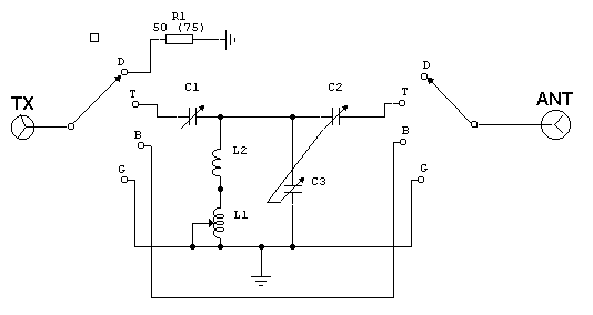
Details - variable capacitors have a capacitance of 200 pF, for the power of 2 kW at the peak of the gap between the plates should be of the order of 2 mm. L1 - coil to the slider, the maximum inductance of 25 mH. L2 - 3 turns of bare wire 3.3 mm 25mm mandrel, the winding length of 38 mm.
Adjustment method:
- for tube-based transmitters set switch to position D (equivalent load), to configure the transmitter for maximum power
- reduce the power to a few watts, set switch to position T(tuner)
- put both of the capacitor to the middle position and adjust L1 to achieve low VSWR, then adjust the capacitors achieving minimum SWR again - adjust L1, then C1, C2, each time achieving a minimum SWR until then, until you have achieved the best results
- apply full power to the transmitter and to adjust all elements within narrow limits. For small capacities of the order of 100 W is well-suited 3-section variable capacitor from an old GSS G4-18A, there is a stand-alone section. Very convenient to use automatic SWR meter.
Here are the possible configurations of antenna tuners who want more to read the article, which discusses their advantages and disadvantages can read the QST Aug 81. If there are many, I can send it, but of course in the original language.
Author: I. A. Dobrokhotov (UN7GM); Publication: www.cxem.net