


")

To conduct long Amateur links on short waves are widely used directional antennas of various types. Relatively long-entered the practice of the antenna type "wave channel", the simplest of which contain two elements - active half-wave vibrator and a passive reflector. However, the two-element antenna with a passive reflector does not provide a satisfactory radiation.
If the frequencies of TV channels can be put up using multi-element antennas, LW bands (28 MHz) together with the rotating device are excessively bulky structures. In this regard, all the more widely used two-element active antenna with reflector. The fact that the antenna with the power of the reflector have a number of advantages over antennas with passive elements.
Briefly, these advantages are as follows. The gain of a two-element antenna with both active elements is equivalent to the amplification of the full-size three-element antenna with passive Director and reflector. At the same values of the gain of a two-element system easier, simpler in construction and has a smaller moment of inertia and windage. Antenna with active power allow you to get more radiation suppression ago that in the context of Amateur communication is more important than the maximum possible for the given system of values of gain. However, it should be noted that antennas with active power is more complex to configure and more critical to the change of parameters.
The principle of operation of two-element antenna with the power of a reflector is to create a two-phase fields of equal amplitude in the opposite direction of the main emission peak of the system. The use of the active reflector allows to achieve equality of currents in both the antenna elements and the phase difference required for the attenuation of radiation ago. The calculations carried out by well-known formulas of the theory of antennas [1], show that the gain of such antennas 3.4 dB higher than that of the antenna with a passive reflector, and the maximum radiation suppression ago (taking into account the losses in the connecting line) is 40 to 50 dB, while in passive systems, it does not exceed 25 dB. The width of the diagram in the horizontal plane at the level 0,707 E is 58°, and the width of the beam in the vertical plane at the height of the suspension l/2 and the radiation angle of 30° is 32°.
The described two-element active antenna with reflector is a modification of the antenna hb9cv please [2, 3], the scheme of which is shown in Fig. 1. At the optimum distance between the elements is equal to l/8, out-of-phase fields can be obtained by feeding the antenna elements with a phase shift of 225°. A phase shift of 225° in the diet of the reflector is equal to the sum of phase shifts that occur due to the anti-phase of the power system elements (180°) and delays in the supply line (45°).
Fig.1
It should be noted that in the circuit of the antenna [2] given the erroneous data that do not provide the desired phase shift when powered coaxial cable.
The main drawback of this antenna is the difficulty of obtaining the necessary phase shift due to the selected power scheme. Any feeder lines are inherent in the velocity factor associated with its design and used materials used in antenna technology feeder lines the velocity factor usually is 1.05 and 1.66. Therefore, for the scheme of Fig. 1 when powered at the points XX is the desired phase shift (due to the line), is equal to 45°, the obtained value will be dependent on the type of the applied line.
Diagram of the antenna is free from this drawback and allows you to get almost any phase shift between two active elements shown in Fig. 2.
Fig.2
The connection point of the supply feeder for a known velocity factor of the line is easily identified by the following formulas:
dp+da=d+2Dlk,
where d is the distance between the elements;
da - length from the point of turning up to the antenna;
dp - line length from the point of turning to the reflector;
Dlk more constructive lengthening line (10-20 cm) and
where l is the operating wavelength;
y is the desired phase shift;
e - the velocity factor.
To power the antenna is convenient to use coaxial cable, type RK-75-7-11 (for which e=1,52) and coaxial tee type BP-193-f, dividing the power equally between the vibrators. When using tee to better align the needs as connecting lines use a coaxial cable with a characteristic impedance of 150 ohms (type RC-150-4-11 or similar).
When calculating the lengths of the elements of the antenna system (which is 0.5 l for reflector and 0.46 l for the actual antenna) must be taken into account the velocity factor depending on the diameter. The calculated values for the antenna with a diameter of 22 mm and a matching line with a diameter of 20 mm are given in table. 1. Here the dimensions of matching elements.
Table 1
Dimensions of the elements cm
The average frequency, kHz
14150
21200
28500
la
968
647
480
lp
1052
702
519
h
12
9
6
Yes
131
87
66
gp
143
95
71
d
265
177
132
Blank dimensions for the antenna of the 14 MHz band are shown in table. 2.
Table 2
The sheet dimensions
Section 1 (1 piece)
Section 2 (2 PCs.)
Section 3 (2 PCs.)
For the antenna, cm
350
250
180
For the reflector, cm
350
250
200
Outer diameter of pipe, mm
22
20
18
The inner tube diameter, mm
20
18
16
The antenna design shown in Fig. 3. Each element is made of three sections, consisting of dural tubes conjugate diameters, dvigausciesya one another.
Fig.3
Since the outer diameter of a tube is equal to the inner diameter of the second, the system of tolerances does not allow you to drive one tube to another to a considerable depth. So along the tube of smaller diameter is cut to a length of 400 to 500 mm, and then secure the joint. It is necessary to pay special attention to ensuring reliable electrical contact in the place of articulation. The contact failure causes a noticeable degradation of the electrical parameters of the antenna. To help adjust to the ends of the flexible elements tips AMTS alloy-M (Fig. 4).
Fig.4
The elements are fixed on a duralumin pipe 40-45 mm in diameter with a wall thickness of 2 mm.
To stiffen the entire antenna system, it must be escalina nylon fishing line with a diameter of 1 mm (Fig. 5).
Fig.5
Other design features are visible from the photos.
The weight of the antenna system is only 6.5 kg, which makes it easy to mount the antenna to one person.
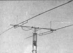
The appearance of the antenna
For rotation of the antenna used motor type PR-1 with built-in inside of the case potentiometric sensor.
Setup antenna system is produced based on the need to obtain a better alignment of the antenna with a feed cable and the maximum suppression of back radiation.
When setting up it is advisable to use the signal from a local source, located approximately in the plane of the elements at a distance of at least 150 - 200 m
The sequence of settings is as follows.
Determine the electrical length of the phase-shifting lines. Measurement and the fit of this parameter should be conducted with accuracy not worse than 2-3 electrical degrees. Changing the length of the matching elements of ya and yp achieve acceptable SWR entire system (not above 1.5 on average frequency range). Adjusting the lengths la and lр, achieve maximum suppression of back radiation. At this stage it is sufficient to achieve inhibition in 20 - 25 dB. Measurements should be undertaken at several points of the range, then re-adjust ya and yp, achieving SWR close to unity.
These operations are performed sequentially several times to obtain the best parameters of the antenna.
Preferably all measurements to produce in the working position of the antenna in order to avoid the influence of the earth, Which at low elevations antenna may distort the results.
It should be noted that the antenna with active elements have a known dependence of the level of suppression of the rear radiation from the corner of the space, which is determined by the difference in the phase relations for waves arriving at different angles to the horizon. For long relationship, when these angles are small, the suppression reaches 40-50 dB.
Literature:
1. S. I. Nadenenko. "Antenna". Wasteheat, Moscow, 1959.
2. "Radio", 1965, No. 11, p. 22.
3. K. Rothermel. "Antenna". Publishing house "Energy", Moscow, 1967.
Author: A. Snesarev (UW3BJ); Publication: N. Bolshakov, rf.atnn.ru