


")

In the modern city apartment to use the radio, especially good, it is almost impossible because of the huge level of interference from a variety of electrical equipment, especially electric vehicles.
Nevertheless, I managed to make the antenna with which the listening receiver start to give pleasure.
This was achieved using the design, which is based on the pipe Central heating or running water. About the use of these tubes in the pages of magazines written about more than once, but, strange to say, never the idea was not developed until the end, and the result or the effect was incomplete, or the idea wholesales at all.
The antenna design shown in Fig.1. The vertical section of a water pipe or heating pipes in girth put on, and then any way, for example with glue and sticky tape, ferrite core shrinks from used transformer line scan tube TV. Previously one of the halves of the core shielded winding is wound with several branches. Here, in fact, all of the antenna device.
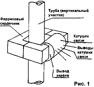
Winding is:
- on the core in one or two layers put any nephroscopy insulating tape (will be used if dry heating pipe, you can take plain paper);
to tape in one layer is made of copper or brass foil, be sure to overlap (overlap) of the coil and put into this overlap (overlap) with the same piece of adhesive tape, to form a solid, closed loop but was not. From the screen make the conclusion. The screen layer of wire does not suit;
- the screen is placed in a single layer winding connection with the taps. I wound 5+10+20 circuit circuit wire cross-section of 0.2 square millimeters;
- on the winding is laid on top of the second foil shield, similar to the first, and both screens are connected;
- all conclusions can be equipped with pins from a suitable connector, or just solder them coaxial cable of the required length. The screens and start winding (the output from the five turns) must be connected to the shield of the cable and connected to the earthing terminal of the receiver, and one of the terminals of the coil connection (to pick up the best work in your favorite range) to connect with Central cable conductor and the slot Antenna of the receiver.
In my experience, the best performance was observed in two bands on pativilca the disqualification, in the medium-wave range at Matnadze-tepidum allotment, and on long waves full on winding connection. With further improvement of the antenna can be entered automatically switching those bends.
But try this and you will not recognize your receiver, so better it will work.
So, what was that in such a simple construction is achieved all of the above effects?
1. Uses existing grounded armature. It gazobetona design, is fully equivalent to the known antennas with top food (ground point somewhere in the basement).
2. The antenna receives the waves with vertical polarization electric vector of the wave radio transmitter, while the horizontally suspended wire electric and mostly household power radiate interference with respective horizontal position of the electric vector of the wave to which the vertical pipe has a lower sensitivity. Take a portable receiver with a whip antenna and, after walking around the city, consider what the position of the antenna of the receiver it is better catches radio station, and if any interference.
3. When the current flows induced by the wave, the tube rings around it (remember the magnetic field of the current flowing through the conductor) is the magnetic field, and the ferrite core antenna concentrates his directing in the winding connection. It's like a transformer from a single turn primary winding - pipe and a selected number of turns of the winding connection.
4. The screens protect the receiver against the penetration of noise through capacitive coupling winding with others radiating objects.
5. The higher the class of the receiver, so as a rule, the better it is protected from receiving signals, in addition to penetrating the antenna, the better it will be to work with this. A good receiver when the antenna to receive a radio station, and even more so interference shouldn't.
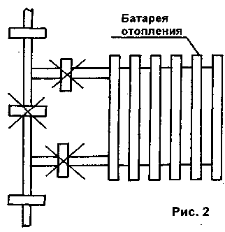
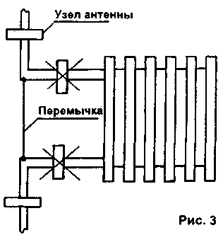
More about some of the features of this antenna. In Fig.2 shows where the aerial device can be placed, and where not, if the radiator bridged the pipe-bridge, and in Fig.3 - if no jumpers. In this case it is better to make artificially by using wire jumpers, mounting wire cross section of at least 1.0 square mm with a thorough its connection to the pipes.
Author: V. Lamar, Severodonetsk, Lugansk region; Publication: N. Bolshakov, rf.atnn.ru