For the reception of television signals in the UHF range, especially in adverse conditions, you must use a good antenna to antenna amplifiers, i.e. active antenna. The experience of construction of such antennas, and says the author the article to be published.
In the UHF range, the effective antenna-feeder system (APS) for receiving signals in difficult conditions has not lost its relevance. The relatively small the length λ of these waves allows you to create high-performance antenna with a relatively small size.
After long experimentation with different antennas the basis was taken famous zigzag antenna [1], shown in Fig. 1. Constructively in classical painting the antenna consists of two identical diamond-shaped parts, rotated relative to one another at 180°. Therefore, this antenna symmetric. This feature permits the use of antenna amplifiers (AU) balanced input and a high gain, for example, plate amplifiers (PAH) SWA and others [2, 3].
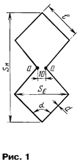
Strengthening zigzag antenna depends on the ratio l/λ, and its input resistance - the relationship l/d and l/λ. Maximum gain is achieved when the length of l = 0,375 λ, but it is highly dependent on the wire diameter.
When l = 0,25 λ amplification is obtained, of course, smaller, but dependence on diameter wire decreases.
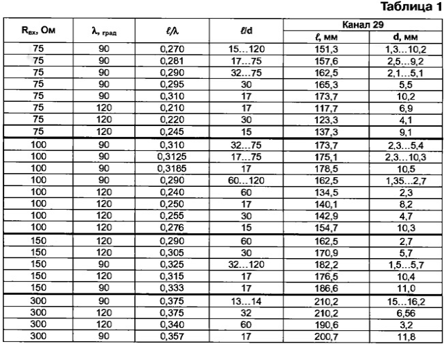
When the angle α change the dimensions of the canvas. So, if α = 90°, then SH = 2√2l = 2,83 l; SE = l√2= 1.41 to l, and if α = 120°, then SH = 2l; SE = 1,73 l. It you need to consider when creating complex ASF (more on this later). Basic dimensions leaf antenna, for example, for the 29-th channel are summarized in table. 1. It should also keep in mind the fact that with decreasing wire diameter and increased perimeter fabric reinforcement increases. In addition, if you choose a thinner wire reduced windage antenna.
Various design antennas have different input impedance (PL. 1). Therefore, the necessary and different ways of matching symmetrical sign paintings with balanced input AE that has an input resistance of 300 Ohms. They are shown in Fig. 2 [4].
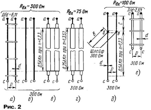
With input resistance of a cloth 300 Ohm AU, of course, you can connect directly to the points a - a. However, to increase the gain and directional action antenna cloth is usually used together with a reflector (it will be below). Therefore, AU is better to install behind the reflector, connecting with canvas symmetric line with a characteristic impedance of 300 Ohms, as shown in Fig. 2,a - for air lines, in Fig. 2,6 - for cable CATV or in Fig. 2, - for cable RC-150. In the latter case, braid the two sections of cable solder one another at the ends.
In all cases it is necessary to consider the velocity factor of the line For K. air line of the wires (Fig. 2,a) - K=0,975, for CATV (Fig. 2,6) - K = 0,8, for cable RC-150 (Fig. 2,C) - K = 0,75...0,86 depending on the type of cable.
The most convenient (in the author's opinion) is to use the canvas with an input impedance of 75 Ohm. In this case, for approval, you can apply a quarter-wave matching transformer from the line with a characteristic impedance of 150 Ohms as depicted in Fig. 2, It is formed of two lengths of cable RK-75 length 0,25 λKn, where n is an odd number. The coefficient K is equal to 0,65789 for cable with polyethylene insulation. The dimensions of the transformer are given by spandam at the ends braids.
The formula for calculating the transformer is known:
Zтр = √Z Input · Zвых ,
so it turns
Zтр = √75 · 300 = 150 Ohms.
Open the matching loop, shown in Fig. 2,d and a quarter-wave transformer (Fig. 2,e) reconcile the AU and the antenna input a resistance equal to less than 300 Ohms. For the manufacture of cable use charts in [4]. The estimated coefficients for the calculation of the plume and the parameters quarter-wave transformer are listed in table. 2. The main requirement for plume - Zл = Zш = 300 Ohms. The dimensions of the plume and the connecting lines are connected the ratio A = B + C.

In Fig. 2,d presents the connection method of the canvas with Rin = 100 Ohm to AY with Rin = 300 Ohms, and A = 0,13 λК, and C = 0,09 λК. To connect using symmetric cable CATV (SLX-300) or an air-line with a characteristic impedance of 300 Ohms. For second case the ratio (D/D) = 6,11. When using wire with a diameter of 3,569 mm the distance between the axes of the wires is equal to D = 21,8 mm. To save fixed distance between the wires placed along the line some cross bracing of high quality insulating materials, which do not deteriorate properties when exposed to the environment (PTFE, polyethylene, organic glass). It should be borne in mind that by moving the loop points in in in and changing the the size, you can achieve a clearer image on the TV screen.
Quarter-wave transformer can be made of pipes with diameter more than 10 mm, as in Fig. 2,i.e. With a smaller diameter, the gap between the tubes is very small that complicate the manufacture of the transformer.
Here is an example of the calculation of the canvas for the 29-th channel. When Fиз = 535,25 MHz'll find λиз = 300 000/Fиз = 560,48 mm. If Rin = 75 Ω and α = 90°, the size of the side diamond-shaped parts (see tab. 1) is equal to l = 0,29 λ = to 162.5 mm, α (l/d) = 32...75. Therefore, the wire diameter of the blade is equal to 2.1...5.1 mm. Can be applied wide strips 2d, i.e. 4,2 10,2...mm, made of copper or duralumin.
Note that all subsequent figures the dimensions are 29-th channel. Conversion to other channels is not difficult: knowing the frequency ratio of the 29-th channel to the frequency of the designated channel of known dimensions is multiplied by this ratio.
Of course, the fabric antenna, in addition to diamond-shaped pieces, can be a other forms, for example, signalisierung with a solid metal sectors, as shown in Fig. 3.
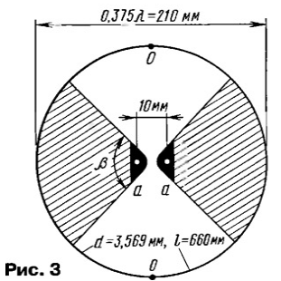
Depending on the angle β canvas has different input impedance. For example, when β = 90° it is equal to Rin = 100 Ω, and when β = 140° - Rin = 75 Ohm. This will determine the different ways of matching fabric with our AU. So, the canvas when β = 90° broadband and more consistent Flex in accordance with Fig. 2, d. When β = 140° antenna will be more narrowband due the necessity of using a quarter-wave matching transformer according to Fig. 2,
For making use of this fabric plates are brass With a thickness of 0.3 mm. reduce sail cloth in each sector drill 15-20 holes 5 mm diameter with a uniform distribution over the area.
The size of the plume for harmonization in Fig. 2, d as follows: a=60 mm, C=40 mm, cuts in from the cable CATV can be long 224n mm, where n=1,2,3.... Quarter-wave transformer of the cable RK-75, in agreement Fig. 2, g may be of length 92,18 mm n, where n = 1,3,5,7....
On the table. 1 you can choose any fabric from 25 proposed based on the availability of materials or other characteristics.
The radiation pattern of the leaf antenna (without reflector) - shift paddle type "g", therefore, the use of the reflector in all cases it is advisable and effectively, as it improves the directional properties and increases the antenna gain by about 3 dB at the design of the reflector, similar to a canvas. However, a more effective way to increase the antenna gain by about 7 dB - install reflex lattice or mesh with small cells. Grille/grid needs to be welded and to have an anti-corrosion coating. The dimensions of the grid/mesh should be 5...10% more vertical (Sн) and horizontal (SE) size canvases.
The grid/mesh is placed on the distance h=100...50 mm behind the canvas based on the received channel (21-69). The value of h affects the input the resistance of the fabric and can serve as an additional way to improve approval of all AFS. Changing h when placing bars on the threaded rods, achieve clearer images with minimal noise ("snow") the TV screen.
The use of reflexive lattice/mesh changes the radiation pattern antenna, turning it into a narrow dnorepository. As a result, the reception side reflector significantly weakened, which increases the noise immunity of the ASF.
Further increase directional and antenna gain can to achieve if you apply the common-mode operation of two or more canvases - common-mode grid. This helps to make the transfer at a considerable distance and in difficult conditions. Such antennas are parallel connected paintings, spaced horizontally and / or vertically in the same plane.
For example, in Fig. 4 shows a common-mode enabling two cloths with the input 150 Ω, spaced vertically. Depicted on the drawing canvas can be considered a modification zigzagoobraznoi antenna with angle β = 0 or a kind of ring. The antenna works well in the UHF range in diameter wire is just 1.5 mm.
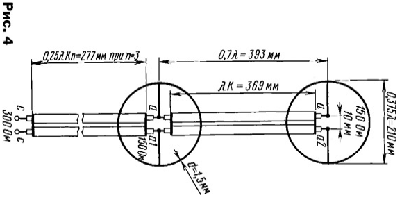
Ways of harmonization of such antenna with AU may be different. Thus, in Fig. 4 shows the option to enable the two webs located at an optimal distance 0,7 λ vertically, with the power line connected to the lower blade (stage). For communication between floors used two-wire line length λК. The line formed two lengths of cable RK-75 (K=0,65789). It is symmetrical and has a wave a resistance of 150 Ohms, which provides good agreement with the canvas.
As a result of this parallel connection of two identical canvases input the resistance of the entire AFC in points a - A1 is equal to 75 Ohms. Coordination with AU made a quarter-wave matching transformer according to Fig. 2, educated two lengths of cable RK-75.
However, it is more preferable (according to the author) another option - Central power. It has a wider bandwidth. Moreover, the cloth can spread both vertically and horizontally to (0,7 0,75...) X between them centers.
To combine paintings at the Central power among them include two series-connected symmetrical lines in Fig. 2,a length of 0.5 HC (184,4 mm spannum braids at the ends), but educated segments of cable RK-75. When this at Central points in the -- in the obtained antenna impedance 75 Ohm. To them and connect the same quarter-wave matching transformer, and Fig. 4.
Similarly, use the blade in Fig. 1 with an angle α = 120°. If used, such paintings with an angle α = 90°, then it is better to spread horizontally.
Common-the inclusion of three similar paintings by Fig. 1 with the Central power depicted in Fig. 5. The grille is equipped with reflex mesh. Input the resistance of each blade is equal to about 100 Ohms, and weakly depends on the diameter wire. To check were used wire diameter 1,2 [(l/d) = 117] 2,76 [(l/d) = 51] mm. the dimensions of the connection lines λК will remain the same, if to use other fabric with Rin = 100 Ohm (Fig. 1 at α = 120° or rice. 3 when β = 90°).
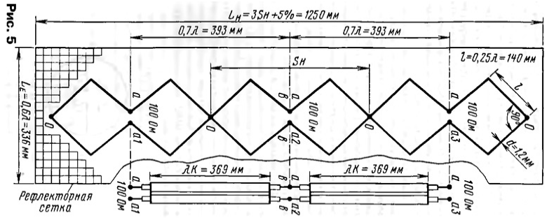
Fabric interconnect symmetrical lines parallel with the wave 100 Ohm, educated segments of cable RK-50 length (spannum braids) equal λК (this condition is mandatory!). At points in a total input the antenna impedance is equal to the 33.3 Ohms. The agreement with AU is provided quarter-wave transformer section of cable RK-50 (Fig. 2,d) length 277 mm.
The canvasses are fastened on the strap made of organic glass with a thickness of 5 mm. To the reflector and the mast strap secured by four threaded studs in 0 points. Reflex mesh (cell size 18x18 mm) is removed from the antenna on canvas the distance h = 105 mm, variable ±15 mm.
As has already been said above, AU set behind the reflector on the mast and connect to the canvas in pixels. the power supply Unit (PSU) AY be placed near a TV or on its rear wall, as shown in Fig. 6.
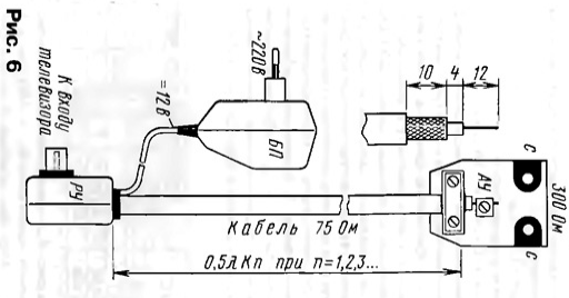
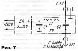
DC voltage of 12 V with power supply is fed via lead-in cable RK-75 via an isolation device (RU), included in accordance with Fig. 7. ROUX consists of inductor L1 and capacitor C2.
Usually PAHs types of SWA, GPS, etc. is fed from a low power PSU that have different schematics, but most are not protected from a short circuit in the load. And such protection is necessary. In addition, if the reception of TV signals comes from different directions, for example, two antennas, switching cables from the antennas to the input of the TV makes a number of inconveniences, and quickly wear out the connectors. It is therefore desirable to provide for automatic switch.
To remedy these deficiencies have been developed by various BP AU. A schematic diagram of one of the variants of PD with the use of relays for automatic switching of antennas is presented in Fig. 8. The strong reception signals provides UHF antenna A1 without the AU connected to the socket XW2, and BP in this case is off. For reception of weak signals, the antenna A2 (XW3) with AU, what happens when the power supply.
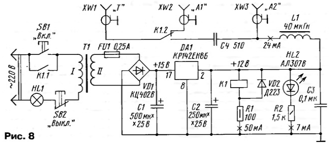
PSU turns on when you press the SB1. This triggers the relay K1 and its the contacts K1.1 block button SB1, holding PSU included. The Contacts K1.2 unplug the antenna A1 and the antenna A2 to the TV. Rectified the voltage displayed by led HL2, with the output of the PSU is held at AU.
In case of short circuit in AU or the feeder voltage at the output of the PSU and the current through the coil K1 of the relay will drop. The relay will release the contacts K1.1, which will shut down the PSU. Led HL2 and the lamp HL1 will go out.
The resistor R1 is selected so that when stabilized voltage of 12V to provide a clear activation of the relay at the minimum current through its winding. The relay can be any, for example, RES (passport RF4.500.409). The lamp HL1 (6.3 In x 0.28 (A) indicates the power supply network and at the same time serves as a fuse in the primary circuit of the transformer T1. Transformer - any voltage at the coil II - 9...11 V. the Inductor L1 is also a favourite, for example, DM-0,6. Chip CREB provides maximum current 1.5 amps and is protected against overcurrent. However PSU consumes no more than 0.1 And, therefore, it is possible to apply a less powerful chip, for example, 78L12.
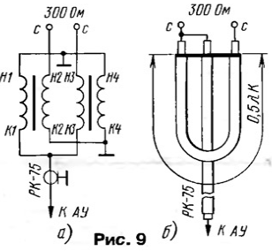
For receiving signals in the UHF range in the magazine considered several AU, for example, [5]. They all have an input impedance of 75 Ohms. They too can use with the described antennas with balanced input. To do this to apply the well-known matching balun device (SSAS) on ferrite the ring, included by the circuit of Fig, 9,and. But you can install SSAS in the form of a U-loop Fig. 9,b. The cable going to the AU, should be short and better length 0.5 λК.
When choosing the installation location of the antenna, you must remember that every extra meter reduce cable will attenuate the signal in the UHF range 0.16...0.4 dB. The thinner the cable the greater the loss. In the final Assembly of the CFA is desirable to install a new cable, since the end of its retention period (defined in 12) the damping factor is increased by 30 to 60%. Cable is better to choose higher frequency, with a larger diameter center conductor. Should to ensure reliable waterproofing in the field of soldering.
Literature
Author: Yu Filichev, Vilnius, Lithuania


