The antenna is designed to work in the first five television channels (50...100 MHz). It has high directivity (8-10 dB) and well consistent with 75 Ohm cable (standing wave ratio of 1.25...2). Such antenna can be used for the reception zone at a distance of 10...15 km. Important characteristics of an antenna are the simplicity of its design, the ability to assemble from readily available materials.
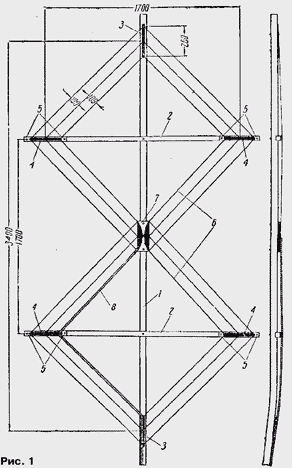
Wooden block 1 section of 60x60 mm (Fig. 1) serves as the Central stand the antenna and mast. To the bar at a 90° angle attached two Reiki 2 section 40x40 mm Top rail fastened to a distance of not less than 1100 mm from the top rack. Reiki is preferably embedded in the center column, and then bonding with her nail or bolt. Directly to the rack on the bottom and top rails are fixed two metal straps 3, the same strap 4, but through a dielectric strip 5 (for example, made of organic glass) mounted on the ends of the rails.
Fee 7 with the feed point located in the middle between the rails; it consists of two rounded metal plates collected on a dielectric strip. After installation of the plates 3, 4 and PCB 7 pull a cloth to the antenna, which consists of three zigzag located 6 wires with a diameter of 2...3 mm (or antenna cord). Wire zigzags parallel to each other. Bends they are soldered to the slats and fins on Board. The antenna feeder 8 points from power is routed parallel to the inner wire fabric, as shown in Fig. 1.

Double zigzag antenna
To increase KND zigzag antenna with reflector, built on its base in-phase lattice. This, of course, the antenna system is complicated and becomes more cumbersome. The most simple common-mode grating it is better to build, using two zigzag antenna.
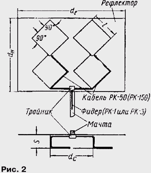
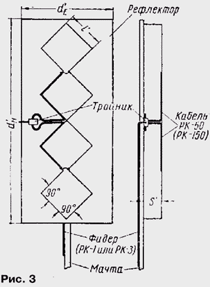
Antenna, forming a lattice, can be positioned relative to each other in planes electric E or magnetic H of the electric field vector. The antenna system of the first type shown schematically in Fig. 2, the second in Fig. 3. To complete the leaf antenna and reflector you can use different materials - thick wires, tubes, strips (preferably copper and brass). You should pay particular attention to routing and connecting the junction cables to the feed points of the antennas.

The dimensions of the antenna in Fig. 2
Channels I-V VI-XII I, mm 1200 343 dE, mm 4980 1420 dH, mm 3500 1000 S, mm 600 170 dC, mm 1920 550 
The dimensions of the antenna in Fig. 3
Channels I-V VI-XII I, mm 1200 343 dE, mm 3000 860 dH, mm 7000 2000 S, mm 600 170For proper phasing of the antennas both screens distribution cables need to be connected to the right (or left) halves of the antenna curtain, and their Central conductors respectively to the left (or right). The connection should not be, otherwise the design will not work. The length of the distribution cables from tee to feed points of the antennas should be the same.
Arrays of both the first and second types of broadband and overlap the frequency range of I to V or VI-XII channels inclusive.
To work in a range of all twelve television channels required two antenna. Their sizes are given in the table.
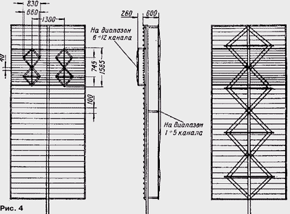
To make full use of band properties of antenna arrays for admission to several television channels and from various directions, you should to provide for the possibility of rotation of the antenna system in the direction of an the telecentre. If telecentres are in the range of I-V and VI-XII of the channels, it is better to make a combined antenna system, twice making target reflector. For the first group of television channels should to perform antenna type H, and the second - type E, increased size. Such a combined system is shown in Fig. 4, which shows the placement antennas relative to each other and the constructive dimensions for small lattice (range VI-XII of channels).
Canvas reflector combined antenna must be placed by the minor the lattice, and against her to lay more wire reflector. They should be located only horizontally, parallel to the intensity vector the electric field of the signal. The power cables are small and large antenna arrays navigate separately (Fig. 2 and 3).
In order to save material and reduce the weight of blade antennas can be achieved not in the three wires, and two, as depicted in Fig. 4. While the CWS supply the feeder has increased slightly.

For the manufacture of the antenna you need the following materials: wooden slats (or bruski), antenna cord (or wire), dielectric (organic glass, ebonite, the plated hardened paper, glass insulators), sheet brass (tin or tinned), cables RK-1 (RK-3) and RC-50 (RC-150). Wood perform frameworks for tensioning antenna curtain wires and reflector, as well as the supporting rack. From cord pull the antenna sheet. In the corners between the conductor and the tree should pave the dielectric plate. The upper and lower corners of the picture attached directly to the frame. Conductors leaf antennas at the vertices of the angles should be close to each other. In the center of the antenna curtain conductors at points their intersection solder with each other.
At the feed point antennas semicircular brass (or tinplate) plate fixed on a dielectric circuit boards to the frame. Antenna feeder tied to the mast and lay it to the Central support rack, which is fixed tee.
Distribution cables are laid through the center of the leaf antenna system, tied up to her inner conductor and is supplied to the feed points of the antennas, where buried in the usual way. On the other side of the canvas is attached a small lattice, which has a similar structure.
The wooden parts of the antenna system to protect against moisture, oil cover paint as in raw wood losing more high-frequency energy.
It is also necessary to remember that the Central wire in the cables RC-50 or RC-150) inside is not fixed, so they should be treated with caution.
After fabrication of the lattice carefully check the power circuit antennas, creating a lattice. If one of the distribution cables will break there, the reception will still be possible, but the efficiency of the antenna system will be worse normal single options.
In the basis of the various options zigzag antennas lies, as already mentioned, aerial fabric. Reflector only reinforces his direction, not missing the high frequency energy in the back half-space. The thicker the conductors from which made the reflector, and the closer they are to each other, the a smaller portion of the incident energy it transmits.
However, for constructive reasons, to do the reflector is not too tight it should. In practice, the distance between the conductors (diameter 2-3 mm) did not exceed 0.05...0.1 of the minimum wavelength operating range.
In the manufacture zigzag fabric you need to pay attention to it symmetry to comply with the terms of the compensation current components on the conductors leaf antenna. Violation of this condition will lead to lower efficiency the antenna system.
Author: K. Kharchenko, Mytischi, Moscow region.


