The problem of construction of a compact television antenna working at all channels VHF and UHF, remains highly relevant. To this end viewers are constantly experimenting with different room, and external antennas. The author proposes another solution to the problem.
Very small and easy to manufacture television sekanina antenna that could be placed on the window or hang on the wall outside, near a window. The basis of the proposed antenna was broadband wave vibrator DM, equipped with split reflector. The last applied yet and as broadband vibrator MB.
As is well known from antenna theory, the dipole has a main resonance (semi ox new) with a length equal to 0,45...0,47 X, where X is the length of the received waves. Point of supply (connection cable reduction) are in the maximum (antinodes) current input resistance g is active and equal to 73 Ohm for a slim vibrator, falling to approximately 50 Ohms for a thick vibrator.
With increasing frequency can be detected and the second resonance (wave), when on each half of the vibrator is placed on the floor of the wave, and the input resistance becomes again active, but very high. It is about W2/r, where W is the characteristic impedance of conductors of the vibrator, defined as the square root of the linear relationship of inductance and capacitance: W = (L/C)1/2 Slim wave vibrator can have resistance to several of the shortfall.
When the detuning away from the resonance frequencies in the input resistance appears and the reactive component, the greater, the more W. For this reason slim vibrators, for example, as in the common room dvukhstruinoi antenna ("whiskers"), do not work in a wide band of frequencies, requiring changes in their length when switching from one channel to another.
For broadband antennas is advantageous to use a thicker vibrators, wave the resistance of which is small (150...300 Ohm). Small and reactive the resistance that appears when nastroika. Decreases and impedance wave vibrator. Moreover, it is not necessary to do surround work well and flat structure made in the form of a lattice of conductors. Such considerations and formed the basis of the proposed design.
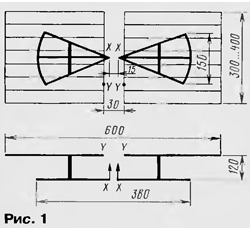
A sketch of the antenna in two views (front and top) are shown in Fig. 1.

Antenna receives radio waves with horizontal polarization coming from the front. Each half of the vibrator is composed of three straight segments of wire with a diameter of 3 5 mm... (the thicker the better) and a length of 18 to 20 cm, fanning Otocec power X - X. the Middle and the ends of the conductors are connected by bridges from the same wire. In the UHF range (at a wavelength of 40...60 cm) vibrator works like a wave.
In the middle half of the vibrator is equipped with metal racks that vibrator attached to the reflector. Electrical contact in places of fastening of racks how to the vibrator and the reflector is required.
Conventional non-resonant reflector would be a solid reflective surface. In the described antenna is made differently: the reflector consists of two parts, each of which has a size slightly larger half-wave UHF. Like this split reflector at UHF.
In the UHF range considering the antenna has a good orientation and provides a gain in 7...8 dB compared with the antenna without reflector.
In the range of MB half reflector addition to the active vibrator and together with him form a single broadband dipole. Directional properties are about like a conventional half-wave vibrator (directional pattern in the form eights). The directional diagram zeros lie in the plane of the vibrator, i.e. lateral directions he takes.
With a symmetric vibrator is best used and symmetrical two-wire feeder line. Well suited ribbon cable with a characteristic impedance of 300 Ohm, but still worth a regular phone wire in plastic insulation ("noodles"), an impedance which is close to 240 Ohms. To align with unbalanced 75 Ohm input on the TV used industrial adapter-transformer 300/75 Ohm on a ferrite ring.
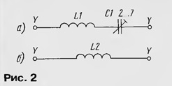
When tested on the ninth floor window facing the telecentre (the distance is about 17 km), the antenna showed excellent results almost at all used in Moscow channels, except the sixth and first. To improve the work the antenna on the sixth channel is managed by including between the halves of the reflector at points Y - The Y position in which the gap is not critical, a series resonant circuit L1C1, shown in Fig. 2,and. It consists of a trimmer capacitor CPC-1 and coils, containing three round 15 mm diameter wire with a diameter of 1 ...1.5 mm. Squeezing or pushing the coils and adjusting the capacitor, to achieve the best image on the sixth channel. The contour of the vibrator turns into a half-wave continuous dipole with a shunt power supply. At frequencies other channels resistance the contour is great and he is not involved in the work.
For frequencies of the first channel dimensions of the vibrator are too small, but there is a way out. Because half of the reflector have a fairly large capacity, vibrator able to set the frequency of the first channel connecting the coils L2 (Fig. 2,b), and even together with the already tuned circuit L1C1. Coil L2 contains 6...8 turns with a diameter of 20...25 mm of the same wire as the coil L1. Set formed by the capacitance of the vibrator and the inductance of the coil circuit and compression the splitting of the turns.

Since the antenna is very broadband, its quite uncritically. For her manufacturers can use a variety of available materials. As reflector, for example, two shelves fit perfectly - from the old grille refrigerator. To increase the mechanical strength at the points X - X and in the gap between the halves of the reflector set with strips of insulating nephroscopes material.
If the antenna is placed on the wall facing the telecentre, the distance from reflector wall to choose (choose) between 0.8...1.5 m to wall has served as an additional reflector on the frequency MB. Another the way to improve the operation of the antenna in the longwave channels (first to third) - one extra split reflector of large size, sealed similarly, as in it is already available.
Author: V. Polyakov, Moscow


