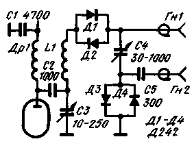
A disadvantage of the previously described electronic switches of the antenna is significant attenuation in the receive mode, reaching 45-50% (especially in ranges 21 and 28 MHz). Switch, diagram of which is shown in the figure, provides attenuation of no more than 10%.

In the manufacture of the switch is necessary to isolate the body of the output capacitor of the P-loop (- C4) from the chassis Teflon or polystyrene lining thickness of 5 mm.
The antenna is connected to the socket GN, the input of the receiver to the socket GN.
Author: Vladimir Davydov (UW9WR), Ufa; Publication: www.cxem.net


