In the previous article of the author (V. Poles. Vertical directional antenna. "LW magazine", No. 5, 1998, pp. 27-31) was described by a two-element directional antenna consisting of two active vertical vibrators. In the process of experimenting with it was invented another way power vertical vibrators, without the use of a quarter-wave two-wire line. Maybe it is to some extent a return to the old and well-known, however the antenna is earned, easily customizable, has shown good results and has been used practically. We offer this design on the judgment to the readers.
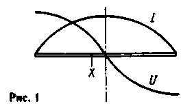
The ideology of this antenna remains ZL-beam with two closely spaced vertical half-wave dipoles, fed almost in opposite phase (phase difference of the currents in the vibrators about 215°). The changes relate to the way power vibrators. Refer to Fig. 1, which shows a continuous half-wave vibrator and distribution of the current I and voltage U in it.

Graphs of these distributions correspond closely to the segments of sine waves. At point X, is offset by some distance from the middle of the vibrator, its resistance in accordance with Ohm's law, is determined by the ratio of voltage to current, R=U/I. It is zero in the middle of the vibrator (because here the voltage becomes zero) and increases in proportion to tg(p/L) at offset feed point at a distance X from the middle of the vibrator. In this way, by the way, is the Windom antenna power single-wire feeder with an impedance of about 600 Ohms. We're gonna need a resistance of about 25 Ohms, so the displacement of the point of supply from the middle of the vibrators will be very minor.
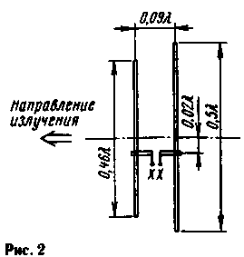
The electrical circuit of the proposed antenna with approximate dimensions given in wavelengths, is shown in Fig.2.

Power cable with wave resistance of 50 Ohms is connected to points Y-Y, providing them with anti-phase excitation. These points connect short thick segments of conductors with dining vibrators X-X. "Thick" wires needed here to reduce their inductive reactance, which, however, will be compensated when setting up the antenna, and as it turned out, no significant effect. For feeder feeder input impedance vibrators are connected in series, so the input impedance vibrators at points X-X and should be around 25 Ohms. With equal success, the antenna can also be coordinated with 75 Ohm cable, just the distance from the middle of the vibrators to points X-X will be a bit larger.
If vibrators were the same, they are excited would be exactly in phase, and the antenna would radiate poorly, with the radiation pattern of two identical lobes back and forth. For proper phasing of the front vibrator is made somewhat shorter than a half wave, and the back is slightly longer (as expected from the reflector). Electrical length of the vibrator in Fig.2 are given with the "natural" shortening vibrators finite thickness. Shortening the front of the vibrator gives a phase shift of about 16° (0.045 L) in the direction of advancing and extending the rear is the same phase shift in the direction of the backlog. The distance between the vibrators is 0.09 L, so the wave front radiated by the vibrator back, turns out to be exactly antiphase wave radiated back back with a vibrator, and both waves are compensated. Therefore, the radiation of the back is missing. The phase difference between the waves emitted by the two vibrators forward, is more than 60°, and these waves are not compensated, forming a directed radiation.
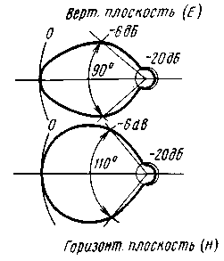
The described antenna has been simulated in the range of 430 MHz as follows: on the record folgero-finished fiberglass dimensions h mm in the middle of the foil was cut and there was soldered cable( Y-Y), braid to the side of the reflector (it is more convenient to call back, the longer the vibrator). Vibrators were made of copper wire with a diameter of 1.8 mm and was attached to the glass-textolite plate spring brackets (X-X), so that the vibrators can be moved vertically. This movement or displacement of the points X-X, has been able to achieve an SWR= 1 at the operating frequency. Suppression of radiation ago was achieved by selection of the lengths of the vibrators. Here's what happened after settings: the gain of the antenna compared with a single half-wave dipole was 5 dB. The directivity in the vertical and horizontal planes is shown in Fig.3.

Fig.3
They are very typical for a two-element antenna and no special features have not. Angle of aperture of the chart on half-power is 110° in the horizontal plane (azimuth) and 90° in the vertical plane (elevation). In the latter case, impact directional properties of vibrators that are in addition to the directional properties of the system of radiators. Evaluation of the winning by the directional diagram gives a value of 6.5 dB relative to isotropic radiator, which fairly well corresponds to the above figure.
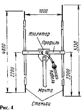
After receiving these results, it was decided to build a portable collapsible antenna for operation in field conditions in the range of 10 m. the sketch is shown in Fig.4. The antenna was raised on a telescopic mast with a height of 6.5 m, made of segments dural pipes in diameter from 24 to 35 mm. To the mast were no radiation field of the antenna, its length should not be a multiple of a quarter wavelength. Although this provision is experimental and untested, a noticeable effect of the mast the specified height for the antenna to work were noted. You can use dielectric masts of any height. The mast was fixed in a vertical position by the stretch of nylon fishing cord. On the upper end of the mast was fixed plate of thick (15 mm) organic glass (insulator), to which the bolt was fastened to the horizontal portion of the supply line. They were made of duraluminium U-shaped profile cross-section h mm profile Dimensions are not critical, so long as it provided sufficient mechanical rigidity of the mounting of the vibrators. Under bolts of fastening of the profile to the insulator were placed petals, which primavalle cable. To reduce the currents flowing in the cable sheath, he was placed two ferrite rings. Electrical contact with the mast cable had.

Vibrators were made of two dural tubes with a diameter of 14 and a length of 3000 mm. both ends of the vibrators nastavlenii Shinigami of the more subtle and very light tube. Stingi could suggest movement and locking screws, adjusting the length of the vibrators. To the ends of the profiles (at points X-X) vibrators were fastened bimkemi of soft aluminum and the screws with the threaded holes in the profile. While the screws are not trapped, vibrators can be moved vertically with some effort, holding the lower mast.
Adjusting the antenna is reduced to the selection of the lengths of the vibrators extension and the insertion of the lower sting. Control of directivity. Practically this is useful when receiving a radio station, the signal from which is stable and comes earth wave. Rotating the mast, see the radiation pattern. The author, experimenting on a garden site in 60 km from Moscow, took the radio Moscow "rescue" ne in the range of 27 MHz, and got the difference when you receive the "front" and "rear" 4...5 points (up to 30 dB). Then the sizes of vibrators were shortened by 4% for reorganisation on 28 MHz. Received acceptable figure, move the vibrators vertically to get a good SWR in the supply feeder. Vibrators while little upset, but all the same operations on the formation of charts and better coordination to consistently repeat a few times. This can be done in the operating position of the antenna, can be opened the mast on one knee, because to get it for adjustment it is only necessary to lower sting both vibrators. In no event it is impossible to touch sting when the transmitter is on, as at the ends of the vibrators are antinodes (maxima) of the voltage and can obtain high-frequency burns. Besides, the antenna gets upset even when you put the hands to the ends of the vibrators. After adjusting the antenna is lowered, tighten all mounting screws and lift again into the working position.
The dimensions given in Fig.4, obtained after adjustment of the antenna. To check the repeatability of the results, other times the antenna was assembled on the ground on the given dimensions and raised without adjustment. The ratio of the radiation back and forward got about 25 dB, and VSWR is less than 2. It took only a small adjustment to the CWS moving the vibrators vertically at their anchorages.
With this antenna experiment was conducted on the reception of signals Scandinavian lighthouses in one day, when passing by a 10-meter range and there was no trace. Setting the receiver on 28,268 MHz and pointing the antenna North-West, the author of one and a half hours patiently listening to pure noise. I must say that the experiment took place in a fairly quiet place, where the noise of the ether, converted to the 50th Board the input of the receiver, accounted for 0.08...0.1 mV in SSB bandwidth of 2.4 kHz. Patience was rewarded with three, one strong and two weaker bursts signal the Finnish lighthouse OH9TEN emitting 20 W vertical omnidirectional antenna. The outbreak lasted from one to four seconds, and there is no doubt that it was a reflection of the signal from the sporadic meteor trails. Subsequent calculations gave values of attenuation meteor signal on this track about 170...dB, i.e. the value that it is possible to block using the radiated power of a few tens of watts, sensitive receivers and the simplest directional antennas, such as described. Thus, meteor link on the "top ten" quite possible!
Author: Vladimir Polyakov (RA3AAE), Moscow; Publication: N. Bolshakov, rf.atnn.ru


