


")

The quality of radio reception in strong interference depends on the antenna. In the article published below: readers are provided with a description of the antenna, consisting of two frames and allows to achieve good reception almost all the broadcasting range.
Loop antenna in the form of a coil, located in the vertical plane, widely applicable to direction finding, broadcasting, radio communications and field-strength measurements in the wavelength range from extremely long to extremely short. However, antijamming radio reception on an ordinary loop antenna at any time of the day when strong interference is difficult because of the existence of the so-called "night of errors" [1]. This happens for the following reasons. First, an obstacle that came at an angle to the horizon, cannot be defeated by a single loop antenna as effectively as an obstacle that came in the horizontal direction. Secondly, the interference suppression decreases with increasing the vertical angle of arrival. To stabilize the plane position of minimum reception and make the minimum directivity zero values in the industry vertical angles of arrival of the wave in a direction-finding antenna used in the form of a United anti-phase [1] posted under.
We offer our readers antenna with diversity framework is designed for connection to a shielded radio receiver with sensitivity not worse than 50 μv and has the following specifications: receiving frequency range is 0.15…24 MHz; the azimuth of arrival of the waves. 360'; the vertical angle of arrival of the wave is About 90…'; interference suppression in a single and common-modes - 0… 30 dB; interference suppression in anti-phase mode is not less than 30 dB; dimensions - HH mm; weight - CNL.
Diagram of the antenna with diversity framework is shown in Fig. 1.
"Fig.1
It consists of two coaxial aperiodic single-turn part of WA1 and WA2, the switch SA1, broadband balun transformer T1 and shielded cable with connector XS for connection to the radio, In the transformer T1 of the transmission line are arranged on a ferrite magnetic wire. Unlike traditional transformer with magnetic coupling between windings, it provides electromagnetic coupling between these lines. The path of the currents from the input contacts X1, x2 of the transformer T1 to a common point at the outlet is equal. The transformer is chosen according to the reference [2]. While preference has been given to its simplest embodiment, with a minimum value of the asymmetry and the operating frequency range of not less than shown in the technical characteristics of the antenna. Connecting the radio with balanced input to pins X1, x2 symmetric antenna output allows you to eliminate the transformer T1. All antenna elements are enclosed in a continuous electric screen from the upper part to the connector XS. Plug-XS shielding circuit of the antenna connects to the radio screen. The clearances of the screen in the upper parts of the framework prevents complete electromagnetic shielding framework.
The antenna can operate in one of three modes: single-player ("O"), in-phase ("C") and antiphase ("P"). In the neutral position "O" of the switch SA1 is enabled single mode. In this case, frame works WA1. When installing the switch SA1 in the "C" frame are connected in-phase and the antenna turns into a double-turn frame. The output level of the antenna is equal to the sum of the outputs of the framework WA1, WA2. Common mode used in the impact on the antenna surface wave interference, and when the signal is weak and in the long-wave part of its operating range. In position "P" switch SA1 is activated antiphase mode. The output level of the antenna in this case is equal to the difference signals from the outputs of the framework WA1, WA2. The difference of levels of the output signal of the antenna modes "C" and "P" decreases with increasing signal frequency, and spatial spacing of the frames along their common axis.
In the "P" eliminates the change of the directivity of the antenna for the wave coming at an angle to the horizon. As a result, the interference suppression that came spatial wave, is equal to the interference suppression, surface wave came. This mode is effective when strong signals in the shortwave part of the operating range of the antenna. Due to the low level of the output signal of the antenna to perform the spatial selectivity of the antenna required high sensitivity shielded radio receiver with switchable antenna. In the "P" direction, the minimum reception is rotated around the vertical axis of the antenna at 90'. The directional characteristics of the antenna becomes four-petalled, which also increases the noise immunity of the reception. In the selected mode the antenna is oriented in azimuth to maximize the signal/noise ratio at the output of the radio.
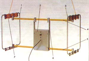
Fig.2
Antenna with diversity framework is shown in Fig. 2. It consists of part 1 and 3 disposed in parallel planes mirror relative to the control panel 2, the upper 4 and lower 5 traverse, two tires metallization 6, two insulators 7 and output cable. The shape and strength of the frame attached to the supporting structure, made of thin-walled steel pipe with a diameter of 8 mm. each frame includes two such pipes having a C-shaped. Their external dimensions h mm. In the cavities of pipes coax cable brand RK75-2-11. The outer conductor of each cable has a gap length of 20 mm in the middle of the top of the frame. The length of the gap equal to the gap between the frame tubes. The inner conductor has no breaks until the switch SA1 on the remote control. The yoke is made of duralumin pipes with a diameter of 16 mm. the length of the upper beam - 670 mm, bottom consists of two parts with a length of 280 mm In the cavity of the tubes of the lower beam wiring from frames included in dural box panel dimensions HH mm Dural bus metallization dimensions HH mm fix the box and connect the upper traverse with shielding elements of the antenna.
Glass fibre laminate insulators dimensions HH mm together with elements 1-6 form a rigid supporting structure. To build applied dural pads and mounting screws M4 and MB. Geometric symmetry, concentricity and parallelism of the framework with the required tolerance of 0.2" shall be subject to the accuracy of the distances between the parts of the framework are not worse than 1 mm. Frame can be moved along the traverse in the Assembly process of the antenna and alignment of the framework. Permissible difference of the lengths of the cables part is 10 mm.
As the mode switch on the remote control used switch P2T-1 with detent in neutral position.
Broadband transformer consists of a ferrite (brand MNN) of the magnetic circuit in the form of three coaxially stacked rings size CHH mm and two cable sections RK75-1-11. Sections of cable are wound in the same direction, forming two windings, each containing eight turns each. The position of the coils is fixed by plastic mandrel with a diameter of 20 and a height of 16 mm, inserted into the cavity of the magnetic circuit. On the cylindrical surface of the mandrel 16 evenly spaced grooves. Each winding occupies eight grooves of the mandrel, which corresponds to half of the ring of the magnetic circuit. The inner conductor of one segment is not used. Prior to Assembly of the transformer with the outer edges of the magnetic circuit sandpaper chamfer 0.3 mm. To prevent electrical interference with the radio, it is important to ensure constant contact between the shielding elements and insulation baffles in those places where the contact should not be.
The manufacturing of the antenna is possible with the deviation from the descriptions. Reserve capacity box allows remote execution of an antenna in various embodiments. From size, number of rings, ferrite materials of the magnetic circuit and the number of turns of windings depends on the value of the upper and lower operating frequency of the transformer, as well as its design. Allowable magnetic permeability of the ferrite is not more than 200. When you lower its value it is necessary to increase the number of rings of the magnetic circuit and the number of turns of the transformer windings. Of the rings, less than CHH mm, you can perform the magni-taproot in the form of a pillar, whose height is limited by the size of the box, the console and should not exceed 180 mm. Transformer with a columnar magnetic core with a height of 126 mm, assembled from rings CBM with a magnetic permeability of 150…200 may contain two windings three turns.
The use of symmetric lines of the wrapped winding wires simplifies the transformer design, but also increases the asymmetry of the antenna circuit.
The toggle switch P2T-1 replace switch of three positions and two directions. The volume of the box of the console allows it pre-amp with the power source and the setting items of the framework in resonance. Noise figure pre-amp must be less than the noise figure of the radio. In a very simplified antenna allowable bearing structure made of wood, and for installation, use a shielded wire having an outer insulation.
The directivity of the antenna in the horizontal plane at frequencies of 8…10 MHz, built in polar coordinates and the same scale is shown in Fig. 3. The measurements were carried out in the receive mode, eliminating interference operating the radio equipment. This was done with variable speed (1 dB) attenuator having a maximum attenuation of 63 dB, shielded radio receiver sensitivity of about 10 mV with Telegraph oscillator and disable AGC and output indicator. When using broadcast receiver with nondisconnectable ARU, apply calibrating measurement method proposed in [W]. To do this, connect to the radio subsidiary ("gage") generator. If the oscillator frequency falls within the bandwidth of the radio and the output voltage of the generator 10… 100 times the level of the input signal, the dependence of the gain controlled stages of a radio receiver from the input signal level is reduced to the error indicator output. The perfection of the shielding of the radio, which means its suitability to work with antenna, check that no reception after disabling the built-in and external antennas.
The screen can be made of foil or other conductive material. Have it on the inner surface of the case of the radio. Around the built-in magnetic antenna it must not form a closed loop. As an indicator of output suitable AC voltmeter. The role of the reference signal
Fig.3
can perform any radiation of a radio transmitter having a stable level and the desired value of the field intensity. The measurements of Telegraph heterodyne radio should turn on and AGC off. In the process of measuring the input signal level of radio support a permanent change in the attenuation of the attenuator and monitored for the indicator output. The reference level of the signal coming from the antenna, produced by the attenuation of the attenuator.
The obstacle penetrating the radio through the power supply from the mains, leads to measurement error. As the relationship of the input level of the radio to the level of noise penetrating into the radio from the network, the error grows. The impact of network interference weaken, nourishing the radio from the mains via the power antijamming or by applying Autonomous power source. Frame focus mode "P" on the maximum suppression of the signal in the direction of the parish which Orient the axis of the minimum antenna reception.
Literature
1. Kukës I. C., Man M. E. fundamentals of radio direction-finding. - M.: Owls. Radio, 1964, p. 286,290.
2. London S.E., S. tomašević, V. Handbook of high frequency transformer devices. - M.: Radio and communication, 1984, p. 100-102.
3. Fradin A. 3., Ryzhov, E. V. Measurement of parameters of antenna-feeder devices. - M.: Communication, 1972, p. 227 to 229.
A. TRIFONOV, St. Petersburg
Author: A. Kuzmenko, RV4LK, Ulyanovsk; Publication: N. Bolshakov, rf.atnn.ru