The author offers readers a modernized version once popular on-Board voltage indicator.
Published almost ten years ago E. Klimchuk side indicator car voltage [1], in my opinion, still remains one of the most successful designs for such appointment. This indicator does not require alteration car dashboard, the evidence is easy to "read". The device allows it is difficult to judge about the basic parameters of the system: storage battery voltage stabilizer. The indicator has worked on my car already more than five years, confirming its usefulness, high stability and reliability.
However, if you apply slightly different implementation of additional modes of operation of a control lamp and take advantage of the appearance on the market items that were previously inaccessible to the radio, you will have the ability to significantly to simplify the display, improved performance, especially when joint work with temperature-compensated voltage stabilizer [2] Number chips decreases from three to one, reducing the number of passive elements, the valid interval of the voltage supply has expanded to 3...30 V.
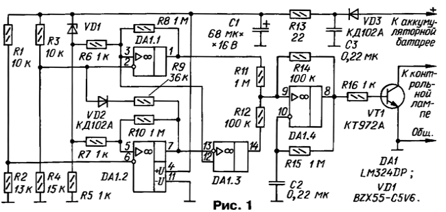
Schematic diagram of the voltage shown in Fig. 1. As in the prototype for the organization of the four modes of operation of a control lamp applied two voltage Comparators at the shelter DA1.1 and DA1.2. The difference lies in the fact that for more upper switching threshold on comparator circuit used high and low output voltage lower by the scheme the comparator. Amplifier DA1.3 inverts the output signal of the comparator DA1.2.

Thus, increasing the voltage at the terminals of a battery the outputs of the shelter DA1.1 and DA1.3 sequentially formed logical combination 01, 11, 00, and 10.
At the OS DA1.4 assembled generator of rectangular pulses, the repetition rate of depends on the values of the circuit C2R15. "Hysteresis" provides voltage positive OS through a resistor R14. Usually such generators "hysteresis" symmetrical voltage switching OS that provide applying a voltage divider R11R12 equal resistance resistors. In this case, the duty cycle at the output of the generator is equal to two.
When you change the ratio of the resistors of the divider "hysteresis", without changing the width of the loop ceases to be symmetric, and therefore, the charging time and discharge of the capacitor C2 is varied, i.e. the duty cycle is changed the pulses. Moreover, if the switching voltage of the comparator exceeds half supply voltage, the duty cycle increases, This principle is used for prompt recognition of two generator modes of operation of a control lamp.
Visual inspection of the indicator showed that at some optimum the oscillator frequency can be obtained in two modes: in one lamp periodically goes out, and the other is periodically switched. It is noticed that when a significant reducing the frequency of fading light (let's call this mode) duration off state of the lamps has become such that in the visual memory violated the integrity of the picture", in other words, the transition of the lamp from the on-state to off and back as if broken into individual elements. It is subjectively did both modes are somewhat similar, and to determine true needed for a second or two to stop the view of the indicator, focus and determine that the lamp is more than the sum of pauses or amount inclusions.
At the same time, the selection frequency achieved to ensure that both modes have become a logical continuation of the adjacent basic status warning lamp - continuous illumination and its absence.
So, if when the ignition is on, but when turned off the starter and idle the engine (I position ignition switch), the lamp is lit, it indicates that battery pack, and if discharged, in moderation.
If in a constant glow lamp failures appear brightness, battery needs recharging.
A similar pattern is observed when the engine is running. If the voltage produced by the generator is within range, the lamp is turned off and does not distract the driver. As soon as the voltage exceeds a threat to electrical level, will begin uniform short flash control the lamps.
Naturally, the same is true if selected thresholds comparison, i.e. values of voltage, which occurs when changing modes the indication. When specified on the diagram the values of resistors R2, R4 and R9, the rapids approximately equal to 12.2, to 13.6 and 14.4 V.
However, it should be noted that the values of the oscillator frequency is still uneven, although in line favorable for psychological perception of the combination. Thus, the frequency of the extinction of the lamp is slightly lower than the frequency of incorporation (if specified in the diagram the values of the passive elements is about 1.2 and 1.5 Hz, respectively).
The operation mode of the generator occurs as a result of changing the polarity voltage divider R11R12-levels 01 and 10 at the outputs of the shelter DA1.1 and DA1.3. If output levels are the same (11, 00), the oscillator is inhibited and the shelter DA1.4 works the voltage follower, i.e. at its output high or low the tension. When running without load, the generator can be brought on parasitic frequency.
Transistor VT1 is assembled current amplifier, loaded with indicator light the filament. In the case of the bulb LEDs turn it on directly between the resistor R16 and the common wire, the anode to the resistor.
A few words should be said about the "hysteresis" threshold comparison. As in the original design, it can be adjusted by changing the ratio of the values the resistance of resistor dividers R6R8 and R7R10. However, the the indicator has a feature related to the change of the load of the generator at the shelter DA1.4. Depending on the mode the output current of the generator may vary from several microamperes to several milliamperes. This leads to a change of the fall the voltage across the resistor R13 smoothing filter C1R13 and therefore threshold voltage. A similar effect, albeit poorly defined, was observed and the prototype [1].
When specified on the diagram the values of parts of the "hysteresis" of the first and third thresholds comparison does not exceed 20 mV, and the second - about 250 mV! The reason is the fact that the average consumption current in the generator and neighboring main the modes are about the same, and the voltage ripple is well suppressed by the filter C1R13.
Greatly reduce the "hysteresis" of the second threshold comparison (to the value less than 40 mV) quite simple - just the positive output voltage operational amplifiers (pin 4) connect to the right (the scheme), the output resistor R13. However, I did not do this, since such the disparity seemed even better.
The fact that the second threshold comparison divides the two, in General, the normal condition of the electrical equipment. On the other hand, possible minor fluctuations in voltage on-Board network near this threshold (in engine idle speed or low tension of a belt of a drive of the generator), given the thermal inertia of the lamp makes it difficult to "read" information. In the same time, small "hysteresis" for extreme values of the controlled voltage provides high accuracy control, which is especially important in determining the degree of discharge of the battery.
Chips instead of LM324DP in the indicator can be used in its domestic analog CAD, you only need to keep in mind that it has the opposite the location of the power pins: pin 4 must be submitted-u pit and conclusion 11 - +U pit [3]. A composite transistor VT1 can be replaced by a regular series of KT815 or CT. The Zener diode VD1 - any for voltage stabilization of 4.7 7.5 In... (for example, KSG, XG, KC168A). The capacitor C1 is desirable to use tantalum (K53-1A, K53-18, etc.). The capacitor C2 (K73-17 rated voltage 63 In) should be chosen as small as possible temperature coefficient capacity.
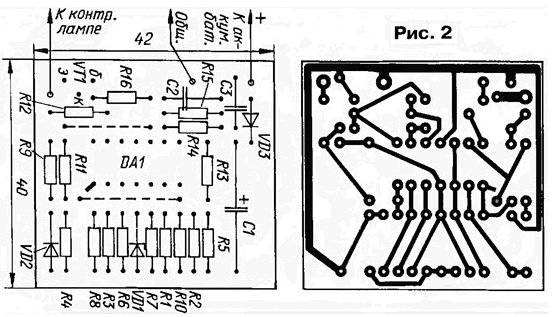
All parts of the indicator are mounted on the circuit Board of foil fiberglass thickness of 1.5 mm. Drawing card is presented in Fig. 2. Cost placed in a plastic box that is attached behind the instrument panel.

The establishment of the indicator is to set thresholds selection of comparison. resistors R2, R4 and R9. How to do this, is explained in detail in [1]. Note only that I think it appropriate to refuse the use of trimmer the resistors. As practice has shown the operation of the indicator, the fine-tuning of the threshold voltage does not occur.
In conclusion, it remains to add that it is useful to try to change a little the frequency of the generator to bring the algorithm indication to a more complete according to the individual peculiarities of perception. To perform this preferably with a lamp of the same type, which will operate the indicator.
Literature
Author: A. Martemyanov, Seversk, Tomsk region.


