About night at the junction of two cars switch high beam headlights of his car in the middle of the first point, the driver perceives as a sharp decrease in the illumination of the road, forcing him to strain and leads to rapid fatigue. Oncoming drivers also harder to navigate the environment at sharp changes in brightness of light from the front. This ultimately reduces the security of the movement.
Significantly reduce the fatigue of the driver during night driving may be smooth (for 3 ~ 4) off beam when you switch it to the middle. Industry produces designed for this purpose, the device of the MDB-1, but he has great size and weight, dissipates considerable power and may not be used on vehicles with halogen bulbs and chetyrehbalnoy lighting system (more on this, see "Without loss of visibility",- driving, 1983, No. 10, p. 30).

Fig.1
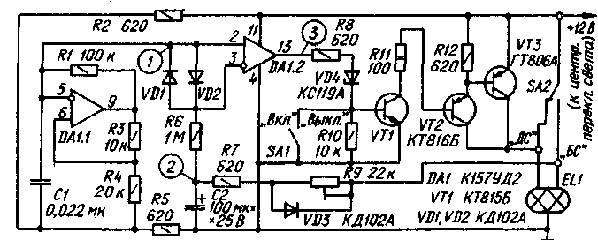
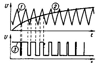
In Fig.1 shows the scheme is free from these disadvantages of the automatic fade-off beam. Timing diagrams of the voltage illustrating the operation of the machine represented in Fig. 2.

Fig.2
Generator operational amplifier DA1.1 generates a triangular voltage with a frequency of 150... 200 Hz (see graph 1 in Fig. 2). which comes to the non-inverting input of op-amp DA1.2. While the main beam (the position of the foot switch light SA2 shown in the diagram), the capacitor C2 is discharged through the resistor R7, diode VD3 and the low beam filament of the lamp EL1 (the diagram shows one lamp two) and the voltage at the output of op-amp DA1.2 about 10.5 V. the Transistor VT1 at this time is open and the transistor VT2. VT3 is turned off, since the collector and the emitter of the transistor VT3 closed contacts of the switch SA2.
After switching beam in the middle of the spiral beam remain enabled through the opened transistors VT2 and VT3. The capacitor C2 begins to charge (graph 2 in Fig. 2) through resistors R7 and R9. The inverting input of op-amp DA1.2 you are increasing the voltage, and the output rectangular pulses of constant frequency and increasing the duty cycle (chart 3). They appropriately switch the transistors VT1--VT3. and the actual voltage on the filaments of the lamps high beam gradually decreases to zero.
When switching lights dipped and main beam, the capacitor C2 is rapidly discharged through the circuit R7VD3. Diodes VD1, VD2 and the resistor R6 serves to limit the voltage between the inputs of the opamps DA1.2; stabistor VD4 and resistors RIO, R12 - for secure closure transistors. Trimmer resistor R9 allows you to adjust the extinction beam in the range from 1 to 4...5 s. the Device may turn off the switch SA1.
The described device is connected in parallel foot light switch as shown in Fig. 1. The cross section of the connecting wires is not less than 1.5 mm2.
In the device used resistors OMLT and GPA-16 (R9), capacitors km-5 and K50-6 (C2). Transistor GTA can be replaced by any other in this series or GTA. If consumed spirals beam current not exceeding 10 A (dvukhfaznyi cars with conventional lamps), instead HTA can be used transistors PA, GTA. Instead of the transistor CTB suitable CTV, CTG or GT, GT with any letter index; instead CTB - CTV, CTG. CTB, CTV. CTG, CTB. Stabistor XA can be replaced by three series-connected diodes KDA or D, D, CDA. To replace the chip CUD undesirable, as it is able to operate in a wide range of supply voltage.
All the parts except the toggle switch SA1, serves on the Board of fiberglass dimensions HH mm Installation made using tinned brass sleeves, flared holes in the Board. Transistors VT2, VT3 mounted on a heat sink with a surface area of at least 40 cm . Assembled device is fixed under the dash left of the steering column.
Immediately after switching the light beam brightness abruptly decreases slightly because of that. what filament lamps are included through the open resistance of the transistor VT3, and then the lamp gradually fade away.
The device can also be used on vehicles with a vehicle voltage of 24 V. this requires in series with the resistor R11 to include a resistor ALT-2 resistance 120 Ohm. replace stabistor XA the Zener DG and use the capacitor C2 to the voltage of 50 V. the Device was tested on the GAZ-24 and showed good results.
Author: Khrisanov; Publication: N. Bolshakov, rf.atnn.ru


