


")

The figure shows a schematic diagram of a universal measuring instrument motorist. Depending on the position of the switch of the kind of work they can check the voltage built-in Autonomous power supply, faulty electrolytic capacitors, the voltage of the battery, the ignition timing, the rotational speed of a crankshaft of a four-cylinder and six-cylinder engines.
In addition, in any position of the switch type of operation S1, you can check low-impedance circuits.
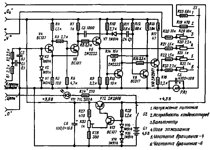
As can be seen from the figure, to increase the stability and accuracy of the measurement results of the electronic part of the device is powered by a galvanic battery G1 via a voltage regulator transistors V12, V13. As a source of reference voltage is used parametric diode stabilizer (V14 - V16). The value of the stabilized voltage of 3.5 V can be adjusted continuously variable resistor R33. When measuring DC voltages (switch S1 in position 1 or 3) milliammeter in conjunction with resistors R25 and R20, R29 forms a DC voltmeter. When checking the health of external circuits instead of the milliammeter indicator led is V11, which is included in series with the battery G1 through resistor R34. Break the circuit being monitored is connected to terminals "Chains" and "0".
The principle of measurement of the ignition timing and the rotational speed of the crankshaft of the engine is to measure the temporal characteristics of the pulse voltage, the current at the terminals of the breaker ignition system of the engine. Thus, the frequency of occurrence of the pulses is directly proportional to the rotational speed of a crankshaft of the engine and is inversely proportional to the number of cylinders, and the angle of rotation of the shaft, wherein the breaker is in closed condition, is directly proportional to the ratio of pulse duration to the period of repetition.
When connecting the breaker contacts to terminals "breaker" and "0" (fourth position S1) pulse voltage is filtered from additional high-frequency noise with a low pass filter (R1, R2, C1, C2). limited to a diode limiter (V1 - V3) I then supplied to the input of the Schmitt trigger (V4 - V5). The duration of the output pulses of the trigger at that accurately corresponds to the time of rotation of the motor shaft when the closed breaker contacts, and the pulse repetition period is the time between the occurrence of sparks in each cylinder Because the amplitude of the pulses at the output of the trigger is constant, then the average value of the output current of the emitter follower (V7) will be directly proportional to the angle of rotation of the shaft at which the breaker contacts are closed.
By measuring the frequency of rotation of the crankshaft of a four-cylinder engine (position 5 of switch S1) used a single-shot (V8, V9), which is triggered by pulses from the output of the Schmitt trigger through the differentiating circuit C3R10 V7R11. The output pulses of the single vibrator stable in amplitude and duration and the repetition period is inversely proportional to the rotational speed. Therefore, the average current through the milliammeter and resistors R22, R31, will be directly proportional to the number of revolutions per minute. To measure the frequency of rotation of a six-cylinder engine switch S1 must be translated in position 6..
The scale of the milliammeter is scaled directly in the measured quantities: direct voltage is 0… 15 V, the angle is 0… 100°: rpm - 0… 3000 rpm Scale of the milliammeter when all the linear measurements. For adjustment of the device must submit to terminals "breaker" AC voltage 24 Q. why do you use a suitable step-down transformer. mains operated.
A trimming resistor R30 set the milliammeter to mark 45° scale angles. Then the resistor R31 in position 5 of switch S1 set the arrow on the scale of the engine speed at around 1500 for a four-cylinder engine and 1000 for six-cylinder.
Sanity check (serviceability) of capacitors made according to the testimony of the milliammeter when connecting the capacitor to the jacks. If the capacitor is defective. then the meter pointer will first rejected then slowly return to the starting position.
From the editors. Transistors V4, V5, V9, V13 can be types CTB. KT315B; V6, V8 - CTB; V10 - MP; -V12 - GTW; led V11 - ALA, the remaining diodes type KD521.
Literature
Publication: N. Bolshakov, rf.atnn.ru